Free-Body Plot and Display
Define visualization options for the free-body plot.
- FBD Plot: Resolve In
- Selects the coordinate system to plot free-body displacements and rotations. Options vary depending on the solver.
- FBD Plot: System
- Available if a user-defined system has been selected.
- FBD Plot: Tolerance
- Displacements and rotations with an absolute value lower than the tolerance are not displayed.
- FBD Plot: Translation
- Defines what displacement component will display.
- FBD Plot: Rotation
- Defines what rotation component will display.
- FBD Plot: Show values
- Defines if free-body vector values will display.
- FBD Plot: Summary table
- Creates tables with free-body displacements and rotations for the selected
sets and loadcases.
Figure 1.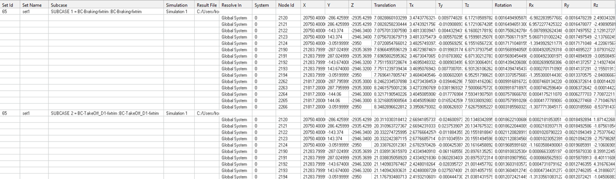
Figure 2. - FBD Plot: Load Creation
- Creates an include file where free-body displacements and rotations are properly realized as loads (enforced displacements) for that model for selected sections and selected loadcases.
- FBD Plot: Create Fields
- Creates field entities with free-body displacements and rotations for the selected sets and selected loadcases.
- Display: Size Scaling
- Defines how free-body vectors will be scaled for visualization.
- Display: Arrow Length (%)
- Scales free-body vectors for visualization.
- Display: Color
- Change the color of each force or moment component.
- Display: Vector Heads
- Defines if the free-body vector points to the node or out of it.
- Display: Vector Style
- Change the style of free-body vectors.
- Display: Numeric Format
- Defines what free-body vector values will be displayed in fixed or scientific format.