The Shell To Solid Conversion tool provides functionality to generate solid elements
and material orientations from a ply based shell model.
Restriction: Only available in the Nastran,
Abaqus, and OptiStruct solvers.
From the menu bar, click Aerospace > Composites > Shell To Solid Conversion.
In the Select entities field, select entities on which to perform shell to
solid conversion.
Laminates
Plies
In the Solid Elems field, select an option that controls the number of solid
elements generated through thickness.
Create solids for each layer – generate single solid elements for each
input ply layer.
Create single solids for all layers – generate single layered solid
element through thickness. Output is either continuum shell of layered solid
depending on the solver profile, element type setting (can be changed from 2D or 3D > elem types > 2D & 3D panel under penta6 and hexa8) and template property.
Create multiple solids using dummy ply separation – generate multiple
layered solid elements through thickness. The number of layered solid
elements is determined by the number of “Dummy Plies” in the laminate.
Output is either continuum shell or layered solid depending on the solver
profile, element type setting (can be changed from 2D or 3D > elem types > 2D & 3D panel under penta6 and hexa8) and template property.
In the Component field, select the method for controlling solid elements
generated in conversion:
Create comp for each ply – a new component is created for each input
ply
Current collector – all solid elements created are placed in the current
component
Create single comp for all plies – a single new component is
created
Use existing shell component – solid elements are placed in the
component containing the shell element from which they are
generated
Select Fill gaps to create pyra and penta elements to
fill voids created by ply drops.
Select Delete Shells to delete shell elements of
ply-based model after solid elements are created.
Select Create Props to create solid composite properties
assigned to created solid elements.
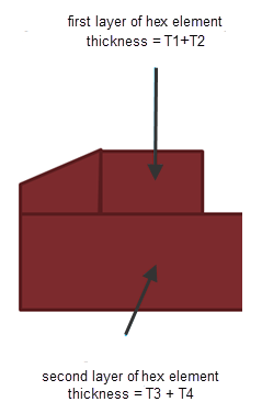
Figure 1. Figure 2. Dummy Ply for Create Multiple Solids Using Dummy Ply
Separation
Convert the Shell Composite Model to the Variable Thickness Solid Layer Composite Model
Develop a composite shell model with Shell_section_composite property. Stop the
procedure with ply realization. Do not convert the ply to a zone based model
using laminate realize.
Change the 3D element type to SC8R and SC6R in the 3D subpanel on the Element
Types panel.
This will assign continuum shell properties to the newly created solids.
Use the Shell to Solid Conversion dialog to select either
Create solids for each layer or Create
single solids for all layers.
Select Current Collector from the Component drop
down.
Check the Fill gaps option for Create solids for each
layer.
Check the Delete Shells option.
Check the Create Props option.
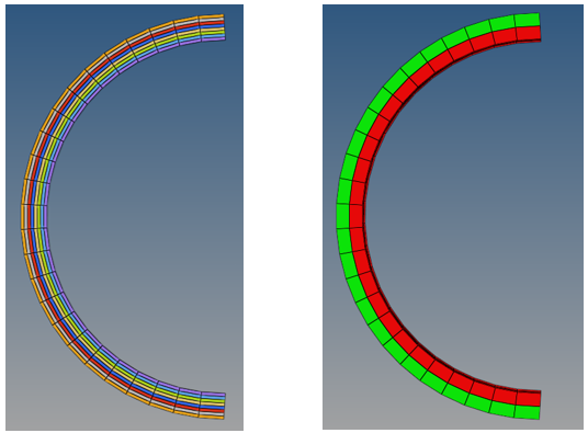
Select all of the plies and click Convert.
This creates a solid composite. You can see the ply direction, even on
the new solid elements.
Note: If you create single solids for all layers,
discontinuous elements may be created near the ply drop off areas. These
nodes should be equivalenced to pass the solver runs.
Create Multiple Solids Using Dummy Ply Separation
Develop a composite shell model with Shell_section_composite property. Stop the
procedure with ply realization. Do not convert the ply to a zone based model
using laminate realize.
Change the 3D element type to SC8R and SC6R in the 3D subpanel on the Element
Types panel.
This will assign continuum shell properties to the newly created solids.
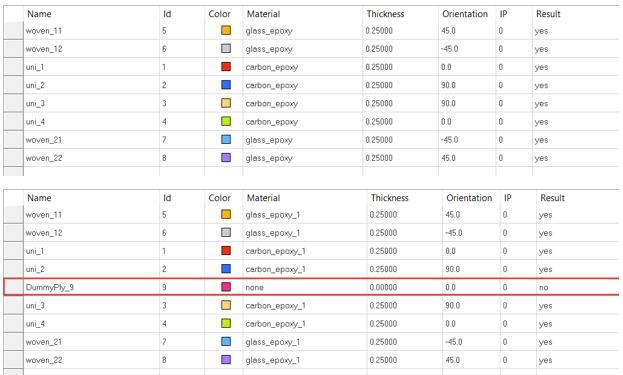
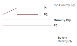
Create dummy plies (zero thickness, zero ply angle) to separate the plies into
a group. You are also required to create top and bottom dummy plies in addition
to the separation dummy plies. Dummy plies can be created using the
Edit Ply dialog and assigning all the elements in the
model to that dummy ply so that it runs through the entire model.
Next, the dummy plies need to be assigned to the laminate. It is required to
add top and bottom dummy plies in addition to inserting separation dummy plies.
This is accomplished using the Edit Laminate dialog.
Select Shell To Solid Conversion from the Aerospace menu
to open the Shell to Solid Conversion dialog. For Solid
Elems select Create multiple solids using dummy ply separation. The Fill gaps
checkbox is automatically selected as long as you define the top and bottom
extra dummy plies in the laminate in addition to the separation dummy
plies.
Select the laminate that is required to be converted and then click
Convert.
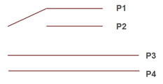
Figure 3. Original Shell Model Ply Figure 4. Original Shell Model Ply Figure 5. Updated Shell Model Plies