Tips for CFD Model Export
Before exporting a mesh for a specific CFD solver, it is advisable to organize the elements into meaningful component collectors.
In the following paragraphs, appropriate element organization and methods to perform organization efficiently are discussed.
If the volume elements are organized in components called fluid or solid, the CFD solver will interpret these names during import and will define general fluid or solid properties for the corresponding volume zones. To complete the setup, you have to specify the detailed properties of the volume zones, for example viscosity, during the usual setup procedure in the CFD solver setup GUI. Multiple fluid zones can be distinguished by an extension, such as fluid_1 or, for solid zones, solid_1.
Generating shell elements on the outer surfaces of the volume mesh and organizing them into collectors is a way to tag boundary regions. If these collectors are called inflow, outflow, symmetry, or wall, the CFD solver will interpret these names during mesh import and define a general boundary condition for each of the regions according to the collector's name. If multiple boundary regions of the same type exist, they can be distinguished by an extension, such as wall_1 and wall_2. Similar to the volume regions, the detailed boundary condition have to be defined in the CFD solver setup GUI.
Figure 1.
This ensures a connected mesh between the volume elements and the initial boundary shells and no further steps are required before exporting the model.
If the boundary shell does not match the volume mesh, additional steps are recommended before exporting the model for a CFD solver. In the following steps, a procedure to organize the model according to the afore mentioned recommendations is described. It might not apply to every model, but it shows the principles.
- Display all elements (In the Model Browser, right-click Component and select Show.)
- Display only 2D shell elements (In the Mask Browser, click 1 in the row for 2D to isolate the shell elements.)
- Delete all display shell elements (some modeling techniques require you to keep certain shell elements; this has to be your decision).
- Show all elements (In the Model Browser, right-click Component and select Show.)
- Display only volume elements (In the Mask Browser, click 1 in the row for 3D to isolate the volume elements.)
- Generate 2D shells on the outer faces of the volume elements (BCs > Faces; select displayed elements and click find faces. A collector called ^faces is created.)
- Create collectors for the volume zones as well as for the boundary regions, for example, fluid and wall (On the CFD Utility menu, click CFD comps and specify in the dialog the required components.)
- Organize the shell elements from the collector ^faces into the corresponding collectors, for example, move the shells from the inflow region into a collector called inflow.
- Organize the volume elements into the corresponding collectors, such as fluid and solid.
- Delete all empty components (, switch the selector to comps, click preview empty and click delete entity).
- Show all elements (In the Model Browser, right-click Component and select Show. Keep in mind that only the displayed elements will be exported in the next step.)
- Export the model for a specific CFD solver.
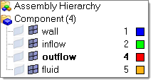
Figure 2.
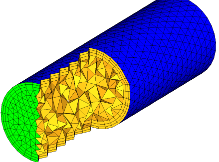
Figure 3.