LS-DYNA Connector Types
Supported LS-DYNA connector types and property/post scripts.
Connector Types
- dyna rigid (crbody)
- Creates a RgdBody element for the body.
- This realization also uses the prop_rigid_crbody.tcl1 property script.
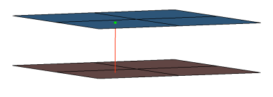
Figure 1.CFG dyna 5 rigid (crbody) *filter spot *head *body 0 rigid 2 1 *post prop_rigid_crbody.tcl - dyna ConNode (spider)
- Creates a ConNode rigidlink element for the body. It connects to the nearest node to the connector position and then projects to the nearest nodes on the adjoining elements of the connected components.
- The dyna ConNode (spider) exists in exactly the same configuration with the
following additional names:
- HC cylinder rigid bolt
- HC cylinder rigid clip
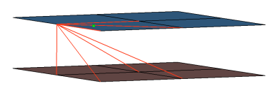
Figure 2.CFG dyna 56 ConNode (spider) *filter bolt *style bolt 2 *head *body 0 rigidlink 1 1 - dyna RgdBody (spider)
- Creates a RgdBody rigidlink element for the body. It connects to the nearest node to the connector position and then projects to the nearest nodes on the adjoining elements of the connected components.
- If holes are detected the nodes on the edges are connected.
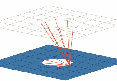
Figure 3.CFG dyna 57 RgdBody (spider) *filter bolt *style bolt 2 *head *body 0 rigidlink 2 1 - dyna RgdBody (spider+washer)
- Creates a RgdBody rigidlink element for the body. It connects to the nearest node to the connector position and then projects to the nearest nodes on the adjoining elements of the connected components.
- If holes are detected the nodes on the edges and the washer nodes are connected.
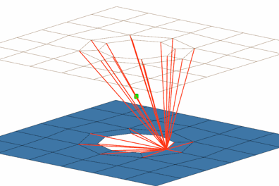
Figure 4.CFG dyna 58 RgdBody (spider+washer) *filter bolt *style bolt 21 *head *body 0 rigidlink 2 1 - dyna acm (shell gap + coating)
- This realization creates one hexa cluster per connector, and realizes a node to node connection to the linked shell meshes by adjusting it (shell coating). Different patterns are available. This is driven by the number of hexas. The appearance can be influenced via the diameter and the washer layer activation.
- This realization uses the prop_acm_coating.tcl2 property script.
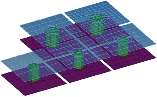
Figure 5.CFG dyna 72 acm (shell gap + coating) *filter spot *style acm 4 *body 0 hex8 1 1 *post prop_acm_coating.tcl - dyna mat100
- Creates a BEAM element for the body and plot elements for the head, the plot elements are created for visualization purposes and find operations.
- This realization also uses the prop_dyna_matnum.tcl3 property script.
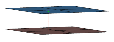
Figure 6.CFG dyna 100 mat100 *filter spot *head *body 0 bar2 1 1 *post prop_dyna_matnum.tcl - dyna mat100 (hexa)
- Creates hexa element with plot elements projecting and connecting to the surrounding shell elements. This realization does not use the shell thickness to calculate the hexa offset, therefore the hexa will project and be touching the shell elements.
- This realization also uses the prop_dyna_matnum.tcl3 property script.
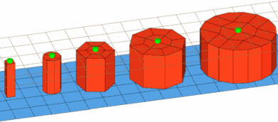
Figure 7.CFG dyna 101 mat100 (hexa) *filter spot *head *body 0 hex8 1 1 *post prop_dyna_matnum.tcl - dyna mat196
- Creates a BEAM element for the body and plot elements for the head, the plot elements are created for visualization purposes and find operations. This realization is the same as the “CFG dyna 100 mat100” realization except it uses Mat196 as opposed to Mat100.
- This realization also uses the prop_dyna_matnum.tcl3 property script.

Figure 8.CFG dyna 102 mat196 *filter spot *head *body 0 bar2 1 1 *post prop_dyna_matnum.tcl - dyna hexa (tapered T)
- Intended to be used for t-cases. The size and exact position can be defined
thickness dependent, or the exact dimension and position parameters can be given.
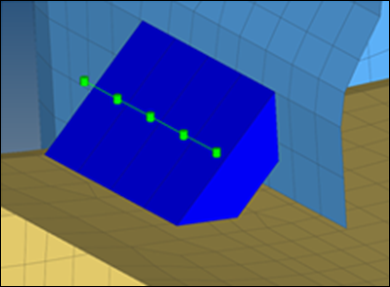
Figure 9.CFG dyna 105 hexa (tapered T) *filter seam *style continuous 6 *head *body 0 hex8 1 1 - dyna hexa (adhesive - shell gap)
- This realization creates rows of HEXA elements for the body. The HEXA elements
project and connect to the adjoining shell/solid elements by touching them.Note: Uses the default parameters, material thickness lookup table, and material strength lookup table from the weld_config.ini config file to set the default attributes for the the created MATL100 material.The dyna hexa (adhesive - shell gap) exists in exactly the same configuration with the following additional names:
- HC glue mastic sealer
- HC glue spot sealer
- HC glue glass adhesive
- The realization uses the
prop_dyna_matnum_seamarea.tcl4 post script.
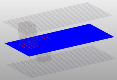
Figure 10.CFG dyna 106 hexa (adhesive - shell gap) *filter seam *style continuous 2 *head *body 0 hex8 1 1 *post prop_dyna_matnum_seamarea.tcl - dyna HC cylinder rigid bolt
- This realization creates a single ConNode rigidlink element for the body, and projects and connects to nodes of the adjoining shell/solid within the prescribed cylinder diameter, L1 (cylinder height along the vector from the connector location) and L2 (cylinder height in the opposite direction of the vector from the connector location).
- The realization uses the prop_dyna_rigidbolts.tcl5 property script.
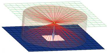
Figure 11.CFG dyna 115 HC cylinder rigid bolt *filter bolt *style bolt 4 *head *body 0 rigidlink 1 1 *post prop_dyna_rigidbolts.tcl - dyna adhesive (shell gap)
- This realization creates a DISCRETE element for the body, and projects and connects to nodes of the adjoining shell/solid elements with ConNode rigidlink elements within the prescribed cylinder diameter, L1 (cylinder height along the vector from the connector location) and L2 (cylinder height in the opposite direction of the vector from the connector location).
- The realization uses the prop_dyna_rigidbolts.tcl5 property script.
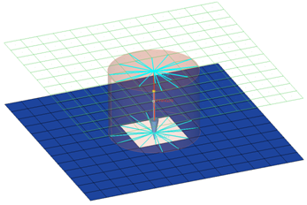
Figure 12.CFG dyna 116 HC cylinder spring bolt *filter bolt *style bolt 4 *head rigidlink 1 1 *body 0 spring 1 1 *post prop_dyna_rigidbolts.tcl - dyna HC cylinder spring bolt
- Creates a row of hexa/penta elements. The hexa/penta elements are projected so that
they touch the shell elements of the connecting components.
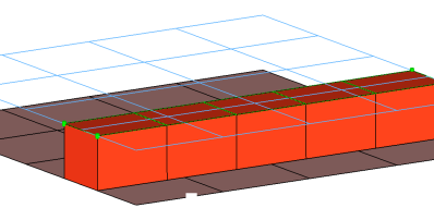
Figure 13.CFG dyna 121 adhesive (shell gap) *filter area *style adhesive 2 *head *body 1 hex8 1 1 penta6 1 1 - dyna - adhesive (shell gap)
- This realization creates rows of HEXA and PENTA elements for the body. The HEXA and
PENTA elements project and connect to the adjoining shell/solid elements by touching
them.Note: Uses the default parameters, material thickness lookup table, and material strength lookup table from the weld_config.ini config file to set the default attributes for the the MATL100 material that was created.This realization uses the prop_dyna_matnum_seamarea.tcl4 post script.
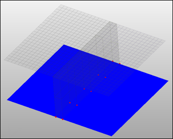
Figure 14.CFG dyna 121 adhesive (shell gap) *filter area *style adhesive 1 *head *body 1 hex8 1 1 penta6 1 1 *post prop_dyna_matnum_seamarea.tcl - dyna - mat196 (single row)
- This realization creates a single row of BEAM elements for the body.Note: Use the init_dyna_mat196.ini config file to set the default attributes for the created MATL196 material.This realization uses the prop_dyna_matnum_seamarea.tcl4 post script and the weld_config.ini and init_dyna_mat196.ini config file.
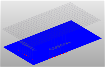
Figure 15.CFG dyna 122 mat196 (single row) *filter seam *style continuous 4 *head *body 0 bar2 1 0 *post prop_dyna_matnum_seamarea.tcl
Automatic Exclusion of Special Nodes During Rigid Bolt Realization
- rigid links
- Rigids
- Rbe3 nodes
- boundaries condition
- IMPDISP
- IMPVEL
- IBVEL
- IMPACC
- FXBODY
- Nodes inside the Interfaces with Type2
Property and Post Scripts
- prop_rigid_crbody.tcl
Updates mesh-dependent rigid welds > 2T into rigidlinks sharing a node. This is a requirement for the LS-DYNA *CONSTRAINED_NODAL_RIGID_BODY definition.
- prop_acm_coating.tclPerforms the following task:
- Organizes the HEXA elements into a set with the name CE_HEXSW_# (# starts with 1 and increments as 1, 2, 3, and so on for every new connector).
- prop_dyna_matnum.tcl
Used during the creation of mat100/mat100 (hexa)/mat196 custom config welds in the Spot panel.
This script performs the following tasks:- Organizes the realized weld elements to the respective components based upon the
link they are connected to and based upon the realization used.
If a weld is created as mat100 between comp_1(id1) and comp_2(id2), it will create a component collector with the name C_^_<id1_id2>_BEAM_100 and organize all of the welds created as links between these two components into this collector.
If a weld is created as mat100 between the three components comp_1(id1), comp_2(id2) and comp_3(id3), it will create two component collectors, C_^_1W_<id1_id2>_BEAM_100 and C_^_1W_<id2_id3>_BEAM_100. The suffix is based on the realization type:- Mat100
- _BEAM_100
- Mat100 (hexa)
- _SOLID
- Mat196
- _BEAM_196
This collector is later referenced as the weld element set while creating the groups (contact) definition.
- This script will create the following properties/materials collectors:
- M_^<id1_id2>_< MAT100 or MAT196> or M_^_1W_<id1_id2_id3>_<MAT100
or MAT196>: These material collectors are created upon the selection of the
configuration type by you with the MAT100 or the MAT196 card. The values for
the cards are read from the *.ini file. These material
collectors are referenced in the above created appropriate
components.
#MATERIAL STRENGTH LOOKUP TABLE
# FIRST NUMBER INDICATES NUMBER OF LEVELS
# SECOND NUMBER INDICATES MULTIPLIER FOR SIGY OF NUGGET
#MIN        MAX         k           n           a           b
#LAST LINE:
#MIN        MAX         k           n           a           b           NUMBER
*SIGY       4           1.85
0           0.20        4.0000      1.9000      10.5000     -4.000
0.20        0.40        4.2000      1.9500      12.000      -3.000
0.40        0.80        4.5000      1.9500      14.200      -2.000
0.80        0.90        4.7000      1.9900      16.500      -1.0000     9.00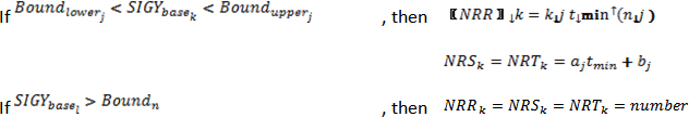
Figure 16. - P_^<id1_id2>_<BEAM or SOLID> or P_^_1W<id1_id2_id3>_<BEAM or
SOLID>: These property collectors are created with the *SECTION_BEAM or
*SECTION_SOLID card associated with them. These property collectors are
referenced in the above created appropriate
components.
# SAMPLE MATERIAL THICKNESS LOOKUP TABLE:
# NUMBER INDICATES NUMBER OF LEVELS
#LAST LINE:
*THICKNESS      5
 0              0.1              0.125
 0.1            0.5               .25
 0.5            1.0               .75
 1.0            1.5              1.25
 1.5            2.0             17.75             2.0
- M_^<id1_id2>_< MAT100 or MAT196> or M_^_1W_<id1_id2_id3>_<MAT100
or MAT196>: These material collectors are created upon the selection of the
configuration type by you with the MAT100 or the MAT196 card. The values for
the cards are read from the *.ini file. These material
collectors are referenced in the above created appropriate
components.
- This script also creates the necessary group (contact) definition upon the
selection of the configuration type. For mat100 and mat196 a group named
C_Contact_Spotweld_<group id> and/or for mat100 (hexa) a group named
C_Contact_Tied_Shell_Edge_To_Surface_<group id> is/are created. These
interfaces are defined with the appropriate solver cards and reference the
following main (MSID) and secondary (SSID) sets:
- For the *CONTACT_SPOTWELD_ID card the following FS and FD are set to 0.1.
- For the *CONTACT_TIED_SHELL_EDGE_TO_SURFACE_ID card FS and FD are set to 0.1 as well. Additionally the values for variable SST and MST in the card image are set to 0.010. These values will override the thickness and establish the tied connection.
- The script creates sets by the name C_S_^Part_<set id>_Contact_<group id>
and C_S_^Weld_<set id>_Contact_<group id>. The configuration types mat100
and mat196 share the same sets, while the configuration type mat100 (hexa) gets a
different pair of sets. The former set contains the parts to which the welds are
connected and the latter contains the weld components created during realization
process. The part sets is defined as main in the appropriate contact definition,
the weld set as secondary.
In addition, for the mat100 (hexa) realization a set for each hexa cluster is created and named CE_HEXSW_<set id>.
All these sets get a card *DEFINE_HEX_SPOTWELD_ASSEMBLY_<# hexa> associated with them.Note: This script is called if the CFG type is mat100/mat100 (hexa)/mat196
- Organizes the realized weld elements to the respective components based upon the
link they are connected to and based upon the realization used.
- prop_dyna_matnum_seamarea.tclThis script performs the following tasks:
- Creates NodesToSurface(Tied interfaces) and names them ADHESIVE_SEAM_CONTACT_PID _# , which references the independent/dependent links' main sets and the nodes' secondary sets (# is the ID of the link components).
- Organizes the link components into a set with name ADHESIVE_SEAM_MAIN_PART_SET_PID_#, which is referenced by the above interface group (# is the ID of the link component).
- Organizes the solids‘ nodes on the links into a set with the name ADHESIVE_SEAM_SECONDARY_NODE_SET_PID _#, which in turn is referenced by the above interface group (# is the ID of the link component).
- Creates a component with the name ADHESIVE_SEAM_MAT100_COMP_PID_#_# for the connector SOLID elements (# is the ID of the link component).
- Creates a property with the name ADHESIVE_SEAM_MAT100_PROP_PID _#_# and SectSld card image, and assigns it to the SOLID component (# is the ID of the link component).
- Creates a material with the name ADHESIVE_SEAM_MAT100_MAT_PID_#_# and MATL100 card image, and assigns it to the SOLID component (# is the ID of the link component).
Note: Uses the default parameters, material thickness lookup table, and material strength lookup table from the weld_config.ini config file to set the default attributes for the created MATL100 material. - prop_dyna_rigidbolts.tclThe script performs the following tasks:
- Organizes the ConNode rigidlink elements into a component with the name Realize#001 (# starts with 2 and increments as 2, 4, 6, and so on for each new connector).
- Creates a view with the name dyna_rigid_bolts.