Results Initializer
Allows you to quickly initialize the sheet metal components in the crash model with stamping history (strain, thickness) but staying within the Engineering Solutions’s Crash pre-processing environment.
The tool can be accessed by clicking the ![]() icon in the Crash
toolbar or by clicking from the menu bar.
icon in the Crash
toolbar or by clicking from the menu bar.
HyperForm's One-Step solver capability is leveraged in this tool for estimation of the stamping history.
- User interface to select the components in the model to be initialized with stamping history and define stamping parameters.
- Ability to conduct One-Step HyperForm analysis for selected components in a batch process.
- Review of the One-Step stamping results in the Crash user profile.
- View available options to saturate higher strains by prescribing cutoff value on max strain and do a rerun.
- Ability to repeat above sequence multiple times on same/different component.
- Strain history information from the One Step is attached to the model as an include file.
- Supported for both solvers Radioss and LS-DYNA.
Invoking the Results Initializer opens a Process Manager tab that guides you through the process seamlessly to initialize the parts with the stamping strain history.
Select Components
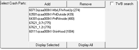
Figure 1.
- Add
- Select the components for intializing from the graphics area or by using the Selector panel.
- Remove
- Remove the selected components by selecting them from the graphics area or by using the Selector panel.
- Display Selected
- Isolate the selected components in the graphics area.
- Display All
- Display all components in the model.
The selected components appear in the Process Manager tab.
Selecting the checkbox for TWB search will prompt the software to check for Tailor Welded Blanks (TWB) among the selected blanks.
Clicking Proceed or Next moves you to the next step.
Review TWBs
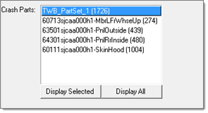
Figure 2.
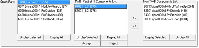
Figure 3.
| TWB Components List | Lists the parts that are auto detected as TWB's for the selected TWB in crash parts. |
| Non-TWB Components List | Lists all other components that are selected by you for results initialization. These are potential components that can be added to the selected TWB. |
| Moves the selected component(s) from the TWB Components List to the Non-TWB Components List. | |
| Moves the selected component(s) from the Non-TWB Components List to the TWB Components List. | |
| Accept | Accepts the changes to the component list of the selected TWB. |
| Reject | Rejects the changes to the component list of the selected TWB. |
| Display Selected | Isolates the selected components in the graphics area. |
| Display All | Displays all of the components in the corresponding list. |
Clicking Proceed or Next moves you to the next step.
Fill Mesh Holes
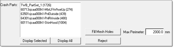
Figure 4.
- Max Perimeter
- Maximum perimeter of the hole that needs to be filled.
- Fill Mesh Holes
- This option temporary fills the holes whose perimeter is less than the value specified in the selected components.
- Reject
- This is a one level undo operation on the hole fill in the selected components.
Clicking Proceed or Next moves you to the next step.
Solve and Initialize Components
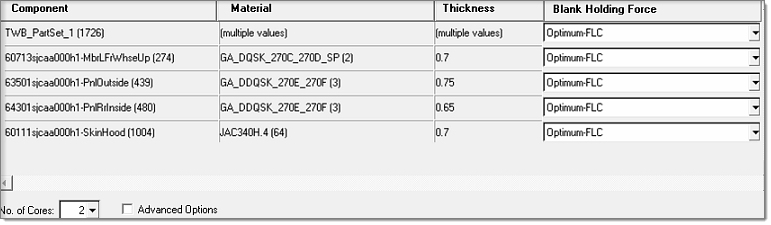
Figure 5.
- No. of Cores
- Define the number of cores used in the initialization process. By default it is set to the number of cores in your desktop.
- Advanced Options
- Selecting this checkbox will add a new Bending/Unbending column to the table that lists all of the components. By default Bending/Unbending will be on for all components.
- Checking the selected components for undercuts
- Exporting the modeling
- Running the HyperForm One-Step solver and
- Importing the results
During this process, the Engineering Solutions session is live. Messages are continuously posted to update you with the status of the initialization process. At the end of this stage, the file that has the result for each selected component are attached as an include file to the model.
Review Results
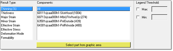
Figure 6.
- Legend threshold option
- The Legend Threshold option allows you to set the maximum and minimum threshold value of the results legend and accordingly contour the results.
-
Figure 7.
Apply Cutoff
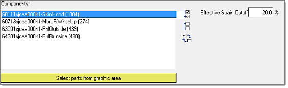
Figure 8.
Click Initialize to rerun the analysis with the cutoff value for the selected components, as explained in the solve and initialize phase. The results from this rerun for the selected components will overwrite the results from the earlier run.
Review Cutoff Results
This phase is similar to the earlier review phase; it allows you to review the results after applying cutoff. This step can be bypassed if phase four is bypassed.
Batch Results Initializer
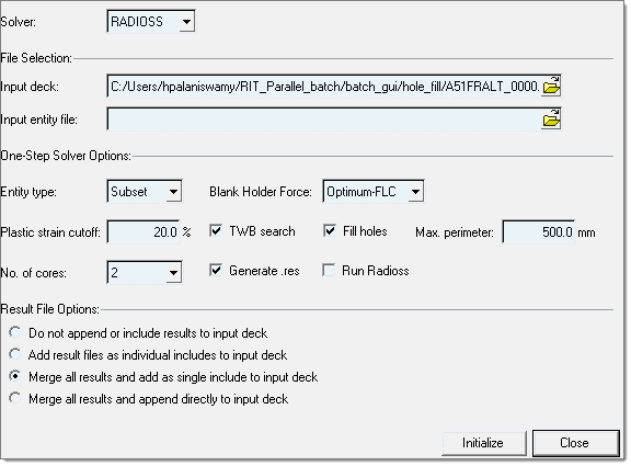
Figure 9.
- Solver
- This is a destination solver of the CAE analysis. Currently LS-DYNA and Radioss are supported. Based on the choice of the solver some of the options change.
- File Selection
- Input deck
- The solver deck that has components/ assemblies that need to be initialized with stamping results.
- Input entity file
- The initialize.dat file that has the components that need to be
initialized with stamping results. This is a text file with four columns with space as
a delimiter.
- Column 1
- Component Name. Ensure that no special characters are used.
- Column 2
- Component ID
- Column 3
- Type. It is limited to Part for LS-DYNA and Part and Subset for Radioss.
- Column 4
- Blank Holder Force. You can choose one of the following: Crash-form, None, Low, Medium, High, Optimum-FLC or Optimum-EPS.
- One-Step Solver Options
-
- Entity type
- You can choose Part for LS-DYNA and Part and Subset for Radioss. These settings will be used if column 3 in the initialize.dat file is blank/undefined.
- Blank Holder Force
- You can choose one of the following: Crash-form, None, Low, Medium, High, Optimum-FLC or Optimum-EPS. These settings will be used if column 4 in the initialize.dat file is blank/undefined.
- Plastic strain cutoff
- This is the max strain value beyond which strain from stamping will be saturated to this value. The value is provided in percentage. For example, a strain value of 0.2 should be provided as 20.
- TWB (Tailor Welded Blank) search
- If this is turned on, a search is performed within components selected for Results Initializer to have potential TWBs. The TWB components are then subjected to one step stamping analysis together.
- Fill holes
- If turned on, the holes on the component are filled and then subjected to one step stamping analysis together.
- Hole fill size
- This field is available only if the Fill holes option is turned on. Provide the maximum size (perimeter) of the hole that needs to be filled before one step stamping analysis.
- No. of cores
- You can define the number of cores available in your computer. By default it will use all the cores in your computer.
- Generate .res
- If turned on, a res file that has the results of all the components chosen for Results Initializer will be created at the end of run.
- Result File Options
- These options are self explanatory.
- Input files
-
- Solver deck that has components that need to be initialized with stamping results.
- Initialize.dat: The list of components in the solver deck that need to be initialized and corresponding stamping information.
- Output files
-
- LS-DYNA: Key file that has the stamping results from Results Initializer.
- Radioss: STA file that has the stamping results from Results Initializer.
Batch Results Initializer and Nesting
Batch Results Initializer and Nesting is a tool that can initialize the sheet metal components in the FE model with one step stamping results and/or do nesting of the blanks from one step stamping results for material utilization in batch mode. Currently it is available for CAD files in the format supported by HyperMesh and the solver decks of Radioss, LS-DYNA, OptiStruct and Nastran. The Batch Results Initializer and Nesting tool can be invoked using the executable LAUNCHRINESTINGGUI.bat/.sh for Windows and Linux, respectively.
- Application
- Select either Results Initialization and/or Nesting by activating the checkboxes. Based on your selection some of the options will be turned off.
- Input file type
- Select either CAD or HM for the input file types for the parts. All CAD formats supported by HyperMesh are supported here.
- Solver
- This is a destination solver of the CAE analysis. Currently OptiStruct, Nastran, LS-DYNA, Radioss and Abaqus are supported. Based on the solver you select the material database needs to be selected. The material needs to be HyperForm One-Step format for OptiStruct, Nastran and Abaqus. The material needs to be in the corresponding solver format for LS-DYNA and Radioss.
- File Selection
- Parameter file
- This is the path of the .csv file that has the following
columns with a comma as a delimiter.
- Column 1
- Part file name for CAD that could be solids as well.
- Column 2
- Thickness: Overwritten with thickness from solids if the part model is solid.
- Column 3
- Material: Name of the material in the database.
- Column 4
- Cost of the material per Kg.
- Column 5
- Blank Holder Force. You can select one of the following: Crash-Form, None, Low, Medium, High, Optimum-FLC or Optimum-EPS.
- Column 6
- The nesting type can be Sheet or Coil. If it is not defined, it is chosen from the GUI.
- Column 7
- The blank fit type can be None, Rectangle, Parallelogram, trapezoid, irregular-trapezoid or Chevron. If it is not defined, it is chosen from the GUI.
- Column 8
- Uniform addendum value all around the blank.
- Column 9
- Blank to Blank edge gap.
- Column 10
- Blank to edge of the coil/sheet.
- Column 11
- The nesting pattern to select from includes One-up (1up), Two- up (2up) or Two-up – Mirror (2up-Mirror).
- Column 12
- The Carrier type to select from includes Single sided (ss), Double sided (ds), Nested (n), Central (c), Double sided and Nested (ds&n), Double sided and central (ds&c).
- Column 13
- Carrier height
- Column 14
- Carrier–Blank gap
- Material file path
- This is the path where the material library is located that is referred to in the .csv file.
- One-Step Solver Options:
-
- Blank Holder Force
- You can select one of the following: Crash-Form, None, Low, Medium, High, Optimum-FLC or Optimum-EPS. These settings will be used if column 4 in the initialize.dat file is blank/undefined.
- Fill holes
- If this checkbox is activated the holes on the component are filled and are then subjected to one step stamping analysis together.
- Max. perimeter
- This field is available only if the Fill holes option is activated. Provide the maximum size (perimeter) of the hole that needs to be filled before one step stamping analysis.
- No. of cores
- You can define the number of cores available in your computer. By default all of the cores in your computer will be used.
- Results Initializer Options
-
- Plastic strain cutoff
- This is the max strain value beyond which strain from stamping will be saturated to this value. The value is provided in percentage. For example, a strain value of 0.2 should be provided as 20.
- Nesting Options
-
- Type
- Select Sheet or Coil.
- Pattern
- Activate the checkbox for One up, Two up or Two up–Mirror.
- Addendum
- Uniform addendum value all around the blank for nesting.
- Part to Part margin
- Part to part margin/gap for nesting.
- Part to Edge margin
- Part to edge margin/gap for nesting.
- Carrier
- If this checkbox is activated select from the carrier types Single sided (ss), Double sided (ds), Nested (n), Central (c), Double sided and Nested (ds&n), Double sided or central (ds&c).
- Carrier Height
- Carrier Height
- Part to Carrier margin
- Distance between the part edge and the carrier.