Nastran Interface
Overview of the Nastran interface.
- Two sub-profiles are available for the Nastran interface:
- Nastran (MSC)
- Nastran (NX)
- During input, the Nastran interface assumes that the continuation line always follows the line before; therefore, no continuation cards are needed in the input file. During export, Engineering Solutions writes "+" or "*" as a continuation card to ensure that the continuation line follows the reference card.
- Warnings and error messages are written to an open text file for your review. You can save this file. All the lines in the input file that are unrecognized by the translator are written to unsupported cards, which can be edited.
- The Nastran input translator supports single, double, free, and fixed formats.
- Two templates are available for export and viewing (editing) Nastran cards. The Nastran/general template outputs all cards in a single precision, fixed format. The nastran/generallf template outputs System, Grid, Element, Load, Subcase, Property, and Material cards in a fixed, double precision (Long) format.
- By selecting the Nastran user profile, you can work with pre-defined panels that are more specific to Nastran usage.
- Symbolic substitution is supported as parameters in Nastran (MSC) for properties and materials. All the attributes in materials and properties can be parameterized.
- Before exporting or editing Nastran cards, a Nastran template must be loaded. Setting the user profile to Nastran automatically loads the Nastran template.
- Engineering Solutions reads and writes certain Engineering Solutions commands in the Nastran bulk data file as comments. These comment cards enable Engineering Solutions to preserve pre-defined preferences across sessions. It is strongly suggested that you do not hand edit these cards.
- A few Nastran solver cards have been migrated from the
load collector entity to the new Analysis Parameters entity with a description of
LoadStepInputs. LoadStepInputs are referenced by the appropriate subcase selectors in
the Load Step entity. These include:
- ACSRCE
- DLOAD
- EIGRL
- EIGRA
- EIGC
- NLPARM
- RGYRO
- RLOAD1
- RLOAD2
- TLOAD1
- TLOAD2
Duplicate IDs
- The Nastran solver interface allows sharing the same ID space between connector elements (RBE2, RBE3, RJOINT, RBE1, GENEL, and so forth), Aeroelasticity panels, and structural elements.
- By default, the Nastran interface doesn’t allow duplicate IDs within the same HyperMesh entity, with the exception of the elements mentioned above. Nastran allows duplicate ID’s across cards mapped to one HyperMesh entity. In HyperMesh, ID flexibility is similar to Nastran and can be enabled by selecting and selecting the allow duplicate IDs option.
- Duplicate IDs are supported for the following HyperMesh entities in the Nastran user profile: elements, properties, and aeroelasticity panel.
- Solver options added in the import browser using renumber the ids to match solver ids, for elements with shared ID spaces, are synced with solver IDs during the import process.
- While HyperMesh post is in batch mode, set the
*templatefilesetcommand in batch scripts to make sure the user profile is loaded upfront. - Refer to the API documentation section for more details on new and modified APIs.
Thermal Surface Elements for Nastran
Engineering Solutions supports the modeling of boundary condition surface elements used in heat transfer solution sequences in Nastran, such as SOL400.
| Thermal Surface Element | Import | Export | Edit | Create |
|---|---|---|---|---|
| CHBDYE | Y | Y | Y | Y |
| CHBDYG | Y | Y | Y | N |
These cards are represented as secondary elements as part of a CONDUCTION, CONVECTION, or RADIATION group in Engineering Solutions, and are created through the Interfaces panel.
Convection
- Group type = CONVECTION
- Group Card Image = PCONV
- Secondary element type = CHBDYE/CHBDYG
- Additional associated cards = CONV: Represented as a checkbox inside secondary element card preview.
Radiation
- Group type = RADIATION
- Group Card Image = RADM
- Secondary element type = CHBDYE/CHBDYG
- Additional associated cards = VIEW: Represented as a load collector in Engineering Solutions
CHBDYE Side Conventions for 3D Elements
To automatically calculate the appropriate value of the SIDE parameter for newly created CHBDYE secondary on solid elements according to the specified face nodes and break angle, go to the Interfaces panel, Add subpanel, and set the secondary option to face.
CHBDYE Side Conventions for 2D Elements
For CHBDYE secondary on 2D shell elements, Engineering Solutions will automatically assign a SIDE parameter value of 1 (top) or 6 (bottom), depending on CHBDYE normal direction. Use the Normals panel (Tool page) to change CHBDYE normal direction.
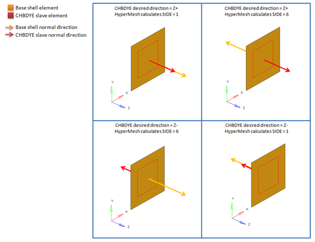
Figure 1. Resulting SIDE Value for CHBDYE Secondary on 2D Shell Element
CHBDYG Side Conventions for 2D Elements
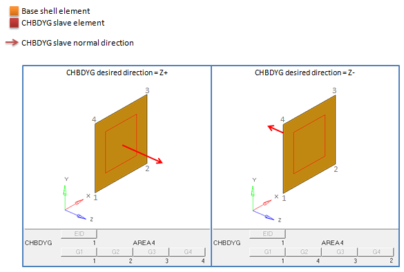
Figure 2. Resulting Node Order for CHBDYG Secondary on 2D Shell Element