Fill Holes, Gaps, Patches

Fill holes, gaps, and patches in first order and second order elements.

  1. From the menu bar, click Mesh > Hole/Gap Fill.
    The Hole/Gap Fill dialog opens.
  2. Select a Fill Type.
    • Choose Hole fills to fills holes and edge loops. Holes can be free edge loops or feature edge loops.


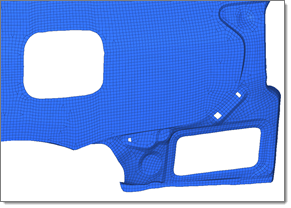
      Figure 1. Free Edge Holes


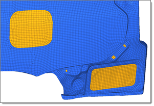
      Figure 2. Free Edge Holes Filled


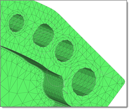
      Figure 3. Feature Edge Holes
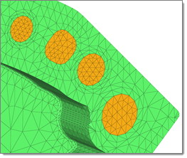

      Figure 4. Feature Edge Holes Filled
    • Choose Gap fills to fill the gaps between a set of elements.


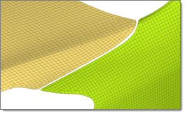
      Figure 5. Gap between Element Sets


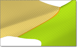
      Figure 6. Gap Filled between Element Sets
    • Choose Patch fills to fill partial edge loops; fills gaps and holes as a pre step for wrapper, where a non-conformal patch can be created to provide a proper input to wrapper.


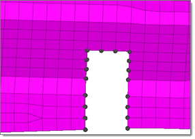
      Figure 7. Partial Edge Loop


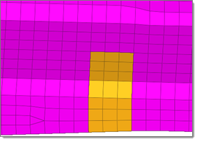
      Figure 8. Partial Edge Loop Filled


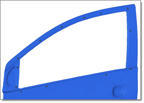
      Figure 9. Gaps and Holes


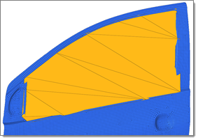
      Figure 10. Gaps and Holes Filled (Non-Conformal Patch)
  3. Use the selector(s) to select the entities which surround holes, gaps, or patches to fill.
    For gaps use the first selector to select entities along one side of the gap, then use the second selector to select entities along the other side of the gap.
    Note: Selection options change based on the Fill Mode selected.


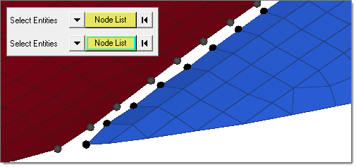
    Figure 11. Node Lists to Detect the Gap
  4. In the Max width field, enter the maximum hole width or gap width to fill.
    Holes/gaps that have a width greater than the specified value will not be filled. Only available for Hole Fill and Gap Fill. In gap fill when node lists is selected, the maximum gap will try to be detected based on the average distance between selected node groups.
  5. Choose a destination component.
    • Choose Current Component to organize newly created patches in the current component. If no current component is defined, a new component “auto” will make created and set as the current component.
    • Choose Adjacent Component to organize the filled/patched elements to the adjacent components. If the hole or gap is shared by more than two components, then newly created elements will be organized in the component with the higher number of nodes around hole/gap.
    • Choose New Component to organize newly created patches in a new component named ^patch.
  6. Define additional options.
    • To remesh the hole/gap/patch around the surrounding elements, select the Remesh checkbox.

      During remeshing, element size, type, and order is determined by the surrounding element's size and type.

    • To mesh/remesh feature loops in holes/gaps, select the Consider Feature checkbox.

      While filling holes, feature holes are also consider and filled. In the Auto detect fill mode, filled feature/free edge holes create intersecting elements with their neighbors, therefore they are discarded and the operation is marked as failed.

    • To fill holes/gaps based on neighboring elements normal, select the Curved Fill checkbox.
  7. Use the Guide Node Pair selector to select two nodes to determine along which direction to fill the hole or gap.
    This is useful when the dimensions of a hole/gap are in two different directions.
  8. Click Fill.
.


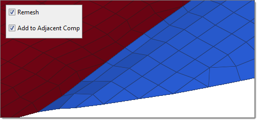
Figure 12. Gap F and Remeshed with Adjacent Components