Create SPH Mesh (LS-DYNA, Radioss, PAM-CRASH 2G)

Create a SPH mesh using existing elements, components, surfaces, or solids in your model.

Before you begin, it is recommended that you create a new component collector before starting the SPH mesh generation so that the generated mesh is stored in a separate collector.
Restriction: The SPH panel is only available in the LS-DYNA, Radioss, PAM-CRASH 2G solver interfaces.
  1. From the 1D page, click sph.
  2. Use the entity selector to select the input which defines the volume to be filled with SPH elements.

    Elements, components, surfaces and solids are supported as input to the SPH mesher. Selected elements can be shell or solid elements; however, the selected elements need to form a closed volume.

    Selected components can contain either a FE mesh or geometry; however, the FE mesh or geometry must also form a closed volume. More than one component can be selected to form a closed volume for SPH meshing. If the selected components are such that one is completely contained within another, SPH elements are created within the volume between the two selected components.


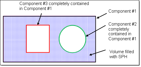
    Figure 1. SPH Elements Created within the Volume between Two Selected Components.
  3. To specify which point the generation of cubes should be started, select the use reference checkbox.

    SPH elements are generated at the corners/face centers of the cubes which fall within the user defined criteria

    • Choose global origin to use the default coordinates (0,0,0) for the reference point.
    • Choose local origin to manually enter node coordinates for the reference point.
  4. Under mesh orientation, define the orientation of SPH elements.
    • Choose global system to use the default global system to align generated SPH elements.
    • Choose local system to manually select reference systems local to the model orientation. Generated SPH elements are aligned using the user defined local system.
  5. Under pitch, select a mesh type and enter a pitch value.
    Pitch is the distances between each SPH particle. Smaller numbers will result in more elements within the same space, but this will not affect the mass or density of the substance (gas, fluid, and so on) that the particles represent.
    • Choose simple cubic to arrange SPH particles in groups of 8, each particle being a corner of a cube.
    • Choose face centered cubic to arrange the particles in groups of 14, forming the corners and the center of each face of a cube.
      Note: This is similar to a hexagonal close packed (HCP) structure and is recommended for use in Radioss models.


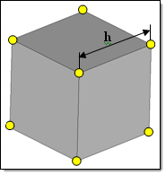
    Figure 2. Pitch (h) for Simple Cubic


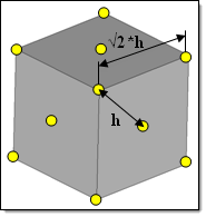
    Figure 3. Pitch (h) for Face Centered Cubic
  6. Define the quantity of fluid.

    Each SPH element must have an effective mass. The effective mass of each SPH element is determined by entering either a material density of the material which fills the volume; or the total mass of the material in the filled volume, called the filled volume mass.

    • Choose material density to enter its density.

      The SPH mesher determines the effective mass for each SPH element from material density, volume to be filled with SPH elements, and number of SPH elements generated.

      Mas s SPHelement = Volume Filled with SP H element Number of SP H element  generated ρ material

    • Choose filled volume mass to enter its total mass.

      The SPH mesher calculates effective mass for each SPH element from filled volume mass, and number of SPH elements generated.

      Mas s SPHelement = Filled Volume Mass Number of SP H element  generated

  7. Under volume definition, specify which elements to generate SPH elements for.
    • Choose all to generate SPH elements in all of the volumes in the model.
    • Choose enclosed to generate SPH elements in the volumes enclosed by the defined nodes, and ignores the remaining volumes.
    • Choose Nth Largest to enter which volumes to generate SPH elements in by defining the wrap size index in terms of volume size.

      To specify the largest volume, enter 1 in the index field; to specify the second largest volume, enter 2 in the index field.

    • Choose exclude enclosed to ignore the volume(s) enclosed by the defined nodes and generate SPH elements in the remaining volumes.
  8. Optional: 
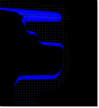
Model a fluid or gas that does not completely fill the selected volume.
    1. Select the partial fill checkbox.
    2. Enter either a percentage or depth of the volume to fill.

      Calculation of the volume is based on the lowest point of the model, parallel to the user defined plane.

    3. Use the plane and vector selector to specify the direction of fill, which is generally the opposite of the direction of gravity when the filled volume is installed in the real world.
    4. If the particle mass is filled along the correct axis, but in the wrong direction (for example from the top of a fuel tank downward), select the reverse direction checkbox to resolve this issue.


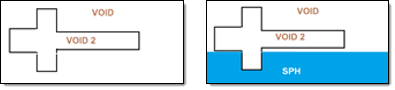
    Figure 4. Partial Fill
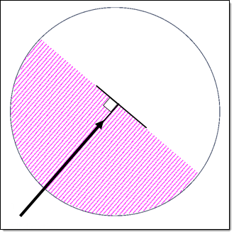

    Figure 5. Fill Direction
  9. Optional: 
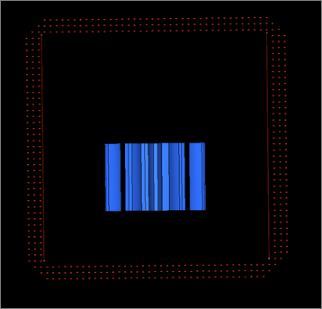
Create SPH particles up to a distance that you specify.

    The thickness of SPH elements is created from input. The distance between the SPH particles is driven by the pitch.

    1. Select the wall offset checkbox.
    2. Enter a distance to offset.


    3. To create SPH particles outside of the defines volume, select the external to volume checkbox.


  10. To create SPH particles from a specified distance, enable the wall clearance checkbox.
    This option is useful when you are trying to avoid contact of SPH elements with walls at the beginning of the solver run (1st iteration) and want the solver to run smoothly.
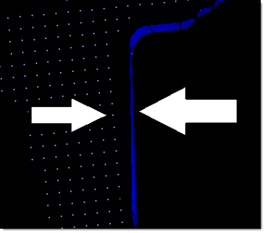

    Figure 6.
  11. Click create.
Tip:

Generated SPH elements (particles) are elements of mass configuration. In the modeling window, SPH elements have a spherical representation and possibly an element handle with an additional label of the element's configuration. To improve visualization of the generated SPH elements (particles), turn off the display of element handles by clicking on the Display toolbar.