Section Browser and Parameter Definition
The Section Browser presents a hierarchical view of all of the beamsections and beamsection collectors in your database.
HyperBeam displays this hierarchy in a standard tree structure of beamsections residing inside of beamsection collectors. Click the ID or config column headings to sort the beamsections and beamsection collectors alphabetically. The Config column lists the type of section: Shell, Solid, Generic and various types of standard sections including Channel, I-Sect, L-Sect, and so on.
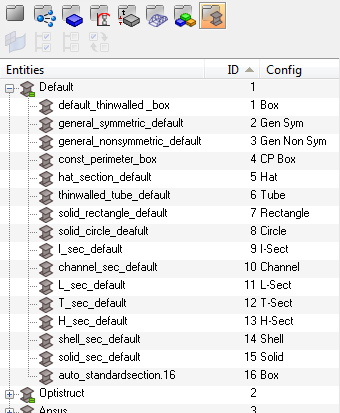
Figure 1.
Context Menu
The right-click context menu contains options for creating, editing, deleting, scaling, welding, and exporting beamsections.
| Option | Description |
|---|---|
| Create | Create a new beam collector, as well as standard, shell,
solid, and generic beamsections. Note: The only standard section
libraries listed are those of the current Engineering Solutions user profile and the Engineering Solutions general standard section
library.
|
| Edit | Opens the Edit Shell Section dialog. The
dialog contains two tabs: Edit Parts and Reorient.
Note: This option is only available for shell
sections.
|
| Scale | Opens the Scale section dialog, from which you can scale the entire beam section by a given scale factor. |
| Copy/Cut/Paste | Choose one or multiple beamsections to copy or cut, and then select a beamsection collector to paste the beamsections to. |
| Delete | Deletes the selected beam collector or standard, shell, solid and generic beam section. |
| Rename | Activates the Entities column of the selected beam collector or beamsection, allowing you to enter a new name. |
| Make Current | Flags which beam collector new beamsections will be created
in. Note: This option is only available for beamsection
collectors.
|
| Collapse All | Closes all of the folders in the Section Browser, so that only the beamsection collectors are displayed. |
| Expand All | Opens all of the folders in the Section Browser, exposing every beamsection nested in every beamsection collector. |
| Auto-weld | Opens the Auto Weld dialog, from which
you can set the tolerance and thickness for the welds. If the
segments or any part are within the tolerance, Auto-weld will
create a new part between them with the given thickness. New
vertices might need to be created to make the connection, which
should be centered at the area where the segments are the
closest. If the thickness is given as 0.0, the connection will
be set to a thickness equal to its length. Auto-weld can also be accessed by selecting the auto-connect shell sections option from the HyperBeam panel > section utils subpanel. Note: This option is only available for shell
sections.
|
| Export CSV... | Captures the beamsection name, each part within the section,
its thickness and each vertex number, and positions it all into
a CSV file. Multiple shell sections can be selected and exported
using Ctrl+left-click, or by selecting Export CSV - all shell
sections from the File menu. This option is particularly useful when you select Import CSV from the File menu, which will read the HyperBeam’s CSV format and create new shell beamsections. The Import CSV and Export CSV options allow you to read and write to HyperBeam without using a .hm file. Note: This option is only available for shell
sections.
|
Parameter Definition Window
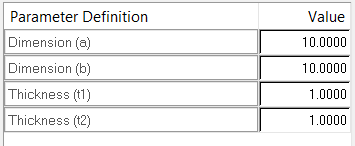
Figure 2. Standard Section Parameter Definition Window
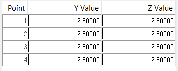
Figure 3. Shell Section Parameter Definition Window