ANSYS Section Macro
The Section macro creates and defines section cards for beam and shell sections.
Create Section Dialog
Create a new beam, shell or pretension section from the Create Section dialog.
Edit Section Dialog
Use the Edit Section dialog to edit existing beam, shell or pretension sections.
Create a SECDATA Card with the Section Macro
-
Click Create to create a section without properties
defined, or Create/Edit... to edit the properties in the
section card before saving.
The following images indicate the location of the value fields in the SECDATA card, such as W1, W2, t1 and t2.
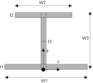
Figure 1. I Beam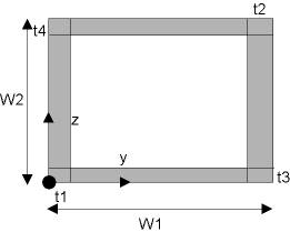
Figure 2. HREC Beam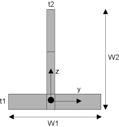
Figure 3. T Beam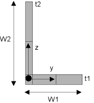
Figure 4. L Beam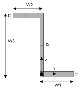
Figure 5. Z Beam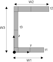
Figure 6. CHAN Beam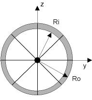
Figure 7. CTUBE Beam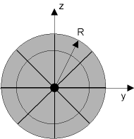
Figure 8. CSOLID Beam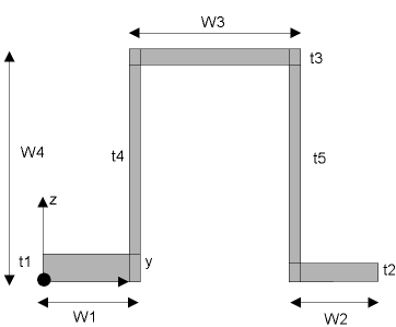
Figure 9. HATS Beam
Figure 10. RECT Beam