Auto Contact

Use the Auto Contact tool to quickly and easily create one or more contact interfaces at once between several parts of your model.

To open this tool, from the Utility Browser, click Tools > Auto Contact or BCs > Create > Auto Contact.
Restriction: This tool is only available when the OptiStruct user profile is loaded.

Based on a proximity distance, the Auto Contact tool will search throughout all of the selected components and automatically create new Contact Surfaces and contact interfaces between them. All of the contact entities found by the Auto Contact tool are displayed and organized inside a temporary Auto Contact Browser, where you can review and adjust them as needed before accepting any changes.

Auto Contact creates OptiStruct CONTACT interfaces, with different type options as available from the Type of Interface pull-down menu in the Auto Contact dialog. The selected Type of Interface will be used as the initial configuration for all found interfaces. Afterwards, you can individually edit the type of interface in the Auto Contact Browser.

Two contact surfaces are created as Main and Secondary entities per contact interface, with the following characteristics:
  • Main and Secondary surfaces are automatically assigned based on the average element size of each Contact Surface:
    • The Contact Surface with the smallest, average element size will be assigned as a Secondary, and the other will be assigned as a Main.
    • The Main and Secondary assignments for each contact can be reviewed and swapped in the Auto Contact Browser.
  • For 3D element faces, the contact surface direction will point outwards from the solid body.
  • For 2D elements, the contact surface direction will be assigned according to element normals, which can be reviewed and reversed in the Auto Contact Browser.

Auto Contact Dialog

The Auto Contact dialog window contains the following options:
Table 1.
Option Description
Type of interface Creates CONTACT interfaces using three different types of interfaces:
SLIDE
Represents a zero-friction sliding contact.
STICK
Represents an infinite-friction sticking contact.
FREEZE
Represents a tied contact.
FRICTION
Represents a contact with friction using a static friction coefficient (MU1).
Select components Directs you to the Component Selection panel, where you can select the components to have the Auto Contact tool search through.
Proximity distance Generates contact pairs between components that are closer to each other by less than the specified proximity distance.
Use shell thickness for 2D elements If activated, the shell thickness values will be used for 2D elements instead of the specified Proximity distance. 3D elements will still use the specified Proximity distance.
Max reverse angle Excludes elements in the contact when the angle between the normals of two elements, or element faces within the proximity distance exceeds the specified reverse angle value.

Default value is 15 deg.

Consolidate contact patches between component pairs Select this checkbox to consolidate any separate contact patch areas that participate in contacts between the same two components, so that the final number of contacts in the model can be reduced. When turned off (default), Engineering Solutions treats each contact patch area as a separate individual contact pair.
Find Executes the Auto Contact search between all of the components in the list.
Cancel Closes the Auto Contact dialog without applying changes.
Remove Selection Icon Removes the highlighted items from the selected components list. You can use the Control and Shift keys to select multiple items in the list.
Review Selection Icon Highlights the selected items from the component table in the Engineering Solutions graphics area, while graying out other components. You can use the Control and Shift key to select multiple items in the list.

Right-click to return the model to normal display.

Help Icon Opens the Auto Contact online help.

Remarks

During the Auto Contact process, temporary components may be created for parts containing 3D elements. These temporary components will be named using a preceding ^ symbol, and will automatically contain extracted element faces needed for the contact creation process. Auto Contact will cleanup and remove these temporary components when you finish or cancel the process. If you decide to export the model before accepting or canceling the process, HyperMesh will always exclude these temporary components from export.

Auto Contact Browser

The Auto Contact Browser provides options for reviewing and modifying contact interfaces and surfaces found by the Auto Contact tool.
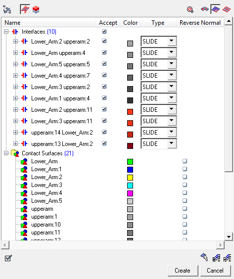
This browser will automatically load in the Engineering Solutions tab area as part of the Auto Contact creation process. All of the entities listed in this browser are temporary, and are not part of the model until you click the Create button. Clicking Cancel will clear all of the temporary entities and close the Auto Contact Browser, leaving your model unchanged. See Remarks below.


Figure 1.

Auto Contact Browser Columns

The Auto Contact Browser contains the following columns:
Table 2.
Column Description
Name Lists the names of all of the contact interfaces and surfaces found by the Auto Contact tool.

Underneath each contact interface name is the temporary master and slave surfaces associated to that interface. Red indicates a slave surface, and blue indicates a master surface.

Renaming entities, as well as Master/Slave surface swapping is possible via the context menu.

Accept This checkbox defines whether or not a contact interface will be included in the creation process once you click Create.
Color Color that will be assigned to the contacts and contact surface entities.
Type Type of CONTACT assigned to each contact interface.
Reverse Normal This checkbox defines whether or not the normal direction of the given surface should be reversed or not. When OFF (default), surfaces on 3D elements will be pointing outwards, and surfaces on 2D elements will point in the direction of the element normal.

Context Menu

Right-clicking on an item in the Auto Contact Browser displays a context menu which offers options for modifying the selected contact interface or surface.
Table 3.
Option Description
Rename Renames the selected entity.
Delete Deletes the selected items from the browser.
Swap Master-Slace Allows you to switch the contact surfaces identified as master and slave. When executed, you will see the surfaces switch places in the master/slave positions in the browser.
Edit Faces Opens the Element Selection panel, where you can manually add and remove individual elements from a selected contact surface. Click Proceed when you are finished.
Note: Only available when selecting contact surfaces.

Also accessible via the Select Elements Manually icon .

Add by Adjacent Automatically adds all of the immediately adjacent elements to a selected contact surface.
Note: Only available when selecting contact surfaces.

Also accessible via the Add by Adjacent icon .

Add by Face Automatically adds all of the elements by face to a selected contact surface. The feature angle controlling face detection tolerance can be modified inside the Options dialog.
Note: Only available when selecting contact surfaces.

Also accessible via the Add by Face icon .

Review Normal Allowed only for surfaces containing 2D elements. For surfaces containing 3D element faces, normal direction is automatically assigned in an outward direction.
Accept All/None Automatically checks and unchecks the Accept checkbox for every item in the Auto Contact Browser.
Reverse Reverses the Accept checkbox status for every item in the Auto Contact Browser.
Expand/Collapse All Automatically expands and collapses every folder in the Auto Contact Browser.

Browser Icons and Other Controls

The Auto Contact Browser contains the following icons and controls:
Table 4.
Option Description
Options Opens the browser's Options dialog. From this dialog you can enter a new feature angle or customize the transparency for a selected entity. Click OK when you are finished.
Highlight Elements When this icon is turned on, the elements that belong to the currently selected contact interfaces or surfaces are highlighted in the graphics area. You can use the Ctrl and Shift keys to select multiple items from the browser.

Highlight Elements is mutually exclusive and may be switched off. This could be helpful when working with large models.

Review Elements When this icon is turned on, the elements that belong to the currently selected contact interfaces or surfaces are reviewed in the graphics area. Elements are highlighted by color, while all other components are grayed out. You can use the Control and Shift key to select multiple items in the browser.

Review Elements is mutually exclusive and may be switch off. This could be helpful when working with large models.

Fit View to Elements Automatically zooms in on the elements that belong to the currently selected contact interfaces or surfaces.
Freeze Displayed Components When this icon is turned off (default), the graphics area will dynamically update depending on the entities that are selected in the browser. When turned on, the current display state will remain unchanged, even when you change your selection in the browser.
Display Components with Elements When this icon is turned on (default), the elements belonging to the currently selected contact interfaces or surfaces are highlighted and reviewed in the graphics area, while also displaying the components they belong to. All of the other components are masked and will not display in the graphics area.
Display Only Elements When this icon is turned on, the elements that belong to the currently selected contact interfaces or surfaces are highlighted and reviewed in the graphics area, while masking everything else.
Select Elements Manually Opens the Element Selection panel, where you can manually add and remove individual elements from a contact surface. Click Proceed when you are finished.

Also accessible via the context menu (Right-click > Edit Faces).

Add by Adjacent Automatically adds all of the immediately adjacent elements to a selected contact surface. Right-click the icon to undo one time.

Also accessible via the context menu (Right-click > Add by Adjacent).

Add by Face Automatically adds all of the elements by face to a selected contact surface. Right-click the icon to undo one time. The feature angle controlling face detection tolerance can be modified inside the Options dialog.

Also accessible via the context menu (Right-click > Add by Face).

Recheck Opens the Auto Contact dialog, so that you can recheck the selected interfaces.

When you select interfaces from the browser, the GUI will automatically populate the components that the interaction was based on. This helps modify an existing interface.

Remarks

During the Auto Contact process, temporary components may be created for parts containing 3D elements. These temporary components will be named using a preceding ^ symbol, and will automatically contain extracted element faces needed for the contact creation process. Auto Contact will cleanup and remove these temporary components when you finish or cancel the process. If you decide to export the model before accepting or canceling the process, HyperMesh will always exclude these temporary components from export.

Set Up an Auto Contact Run

  1. From the menu bar, select Preferences > User Profiles.
    The User Profile dialog opens.
  2. Select OptiStruct as the profile name and click OK.
  3. Open the Auto Contact dialog in one of the following ways:
    • From the menu bar, select BCs > Create > Auto-Contact.
    • From the menu bar, select Tools > Auto-Contact.
    • From the Utility Browser, click the FEA page and select Auto-Contact under the Tools section.

  4. Click the Type of interface menu and then select the type of interface to create.
    The type of interface selected here will be used as initial configuration for all found interfaces, but can be individually edited afterwards in the Auto Contact Browser.
  5. Next to Select components, double-click Component.
    The Component Selection panel opens.
  6. Click Comps then begin to select your components.
  7. Click select.
    The selected components will be automatically placed in the Components list inside of the Auto Contact dialog.
  8. Click Proceed.
    The Auto Contact dialog re-appears.
  9. In the Proximity distance field, enter a value for the proximity distance.
    Contact pairs will be generated between components that are closer to each other by less than this proximity distance.
  10. In the Max reverse angle field, enter a value for the maximum reverse angle.
    If the angle between the normals of two elements or element faces within the proximity distance exceeds this value, the element will not be included in the contact. Default value is 15 deg.


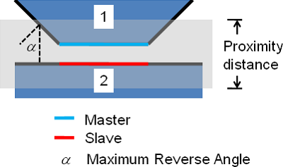
    Figure 2. Definition of Proximity Distance and Maximum Reverse Angle
  11. Click Find.
    The status bar activates. Once it is complete, the Auto Contact Browser automatically opens.
  12. Use the Auto Contact Browser to review all of the found interfaces and make any necessary adjustments to contacts and contact surfaces. When you are finished, click Create.
    Contact surfaces and contacts are created for all items marked as Accepted. Clicking Cancel will close the Auto Contact Browser without creating any contacts.