Building AutoTire Test Rig using the Assembly Wizard
Using the Tire Test Rig, you can test the tire component of you model by running it
under various conditions of Lateral slip, Longitudinal slip, and vertical loads.
Among the various objectives of the test rig, one of them is to cross-check the
performance of the tire models against their property files.
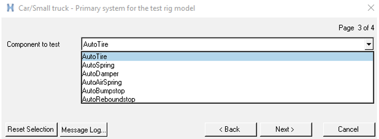
While building the test rig, you can choose the AutoTire option to build a Tire Test
Rig. Figure 1. Building a Tire Test Rig
Topology
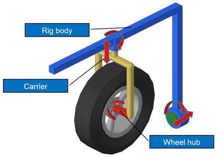
Figure 2. Test Rig Topology
The tire test rig consists of:
Rig body: This is the main structure that supports the tire. This is also
the part that forces translational and camber motion to the tire.
Carrier: The carrier holds the hub and can impose toe/steer and vertical
motion to the tire.
Wheel hub: The AutoTire is attached to this part. Wheel hub acts as the
spindle for the tire and this is mounted on the carrier with a revolute
joint. Spin motion on the tire is imposed using this revolute joint.
Note: In the test rig, the tire is moved on the road
along its surface, while the road is stationary. In Lateral Slip and Vertical
Load tests the wheel rolls freely and in Longitudinal Slip a spin motion is
imposed on the wheel.
Dimensions of the Test Rig
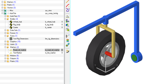
The test rig is parameterized with respect to the “Road_ref_marker”. Figure 3. Road_ref_marker
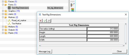
The general dimensions of the test rig can be controlled using the “Test Rig
Dimensions” dataset/form. Figure 4. Editing Test Rig Dimensions
Choosing a Tire Model to Test
You can test any tire model that is supported in MotionSolve.
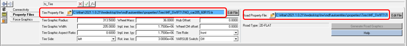
The default can be edited by browsing to the necessary tire and road property file in
the AutoTire panel. Figure 5. Choosing a Tire/Road Property File
Note: The test rig has been designed for testing tires
on flat roads only.