Using the Macro
Execute the CM_synthesis_and_design.lua アプリケーションマクロ in POSTFEKO to calculate the weighted sum for the characteristic modes of interest.
-
Execute the CMA_synthesis_and_design.lua
アプリケーションマクロ in POSTFEKO.
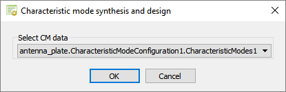
The Characteristic mode synthesis and design dialog is displayed.Figure 1. The Characteristic mode synthesis and design dialog.
-
In the Select CM data drop-down list, select
antenna_plate.CharacteristicModeConfiguration1.CharacteristicModes1
and click OK.
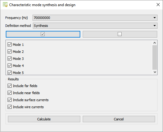
The second Characteristic mode synthesis and design dialog is displayed.Figure 2. The Characteristic mode synthesis and design dialog.
-
Select the modes of interest to calculate the weighted sum.
Tip: Use the
 button to select all modes
and the
button to select all modes
and the  button to clear all
modes.
button to clear all
modes. -
Click Calculate to start the calculation process.
The following dialogs are displayed.Figure 3. The Characteristic mode synthesis and design (progress) dialog.
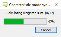 Figure 4. The Characteristic mode synthesis and design (Done) dialog.
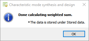
-
View the results under stored data.
Note: The label convention for the synthesis definition methods are:
- Synthesis: <requestname>_SM1__M20.
- Design: <requestname>_DM1__M20.
An example using the synthesis definition method, summing modes 1 to 20 at 830 MHz for the antenna plate example. The results for the far field and currents are shown. The full solution (MoM) is compared with the synthesis method.Figure 5. Example comparing the full solution to the synthesis definition method (using modes 1 to 20) for the far field.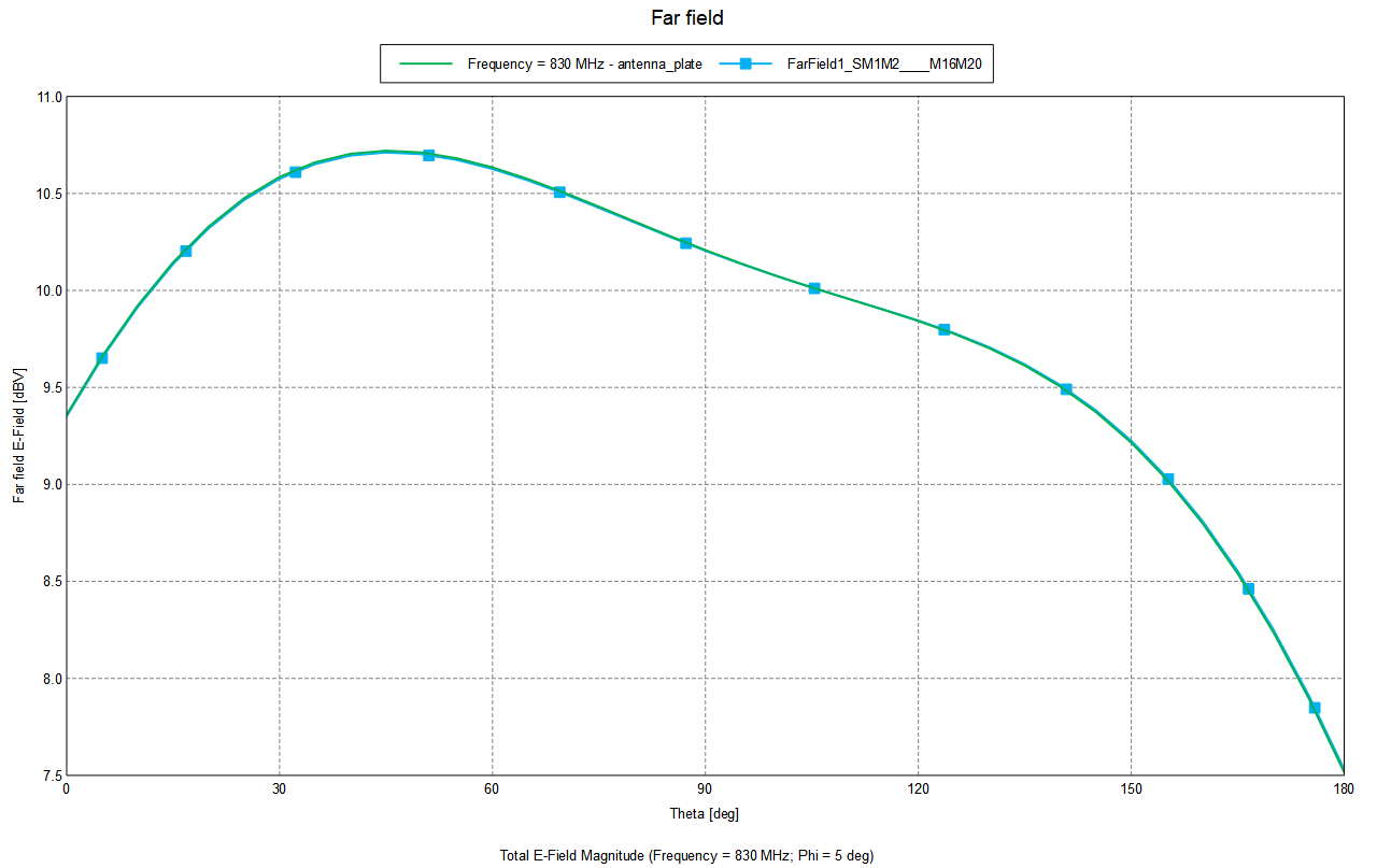 Figure 6. Example of the surface current for the synthesis definition method (using modes 1 to 20).
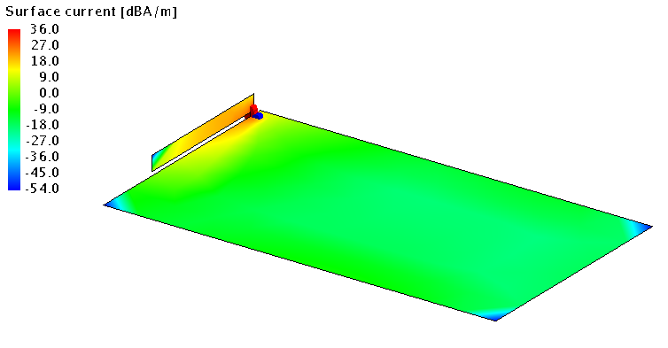 Figure 7. Example of the full solution for the surface current.