Import I-DEAS UNV Mesh
PREFEKO supports the import of mesh files containing segments and triangles from I-DEAS UNV .unv files.

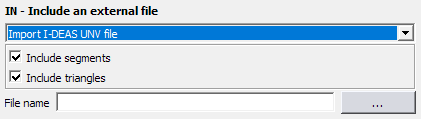
Figure 1. The IN - Include an external file (I-DEAS) dialog.
最新のリリースで新規に追加された機能の紹介です。
Feko Getting Started Guideでは、Fekoをはじめて使用する場合に必要となる部分を手順を追って紹介します。
Feko Example Guideでは、Fekoのコンセプトと基本を学ぶための例題集を掲載しています。
Fekoは、任意形状の3Dオブジェクトを含む電磁界解析に使用される複数の解法を備えた包括的な電磁気ソルバーです。
CADFEKOを使用して、グラフィカル環境で形状またはモデルのメッシュを作成およびメッシングし、解析設定と計算要求を指定します。
POSTFEKOはFekoのポストプロセッサであり、モデル(設定とメッシュ)、グラフ上の結果、3Dビューの表示に使用します。
EDITFEKOは、ループや条件文を含む高水準のスクリプト言語を使用して(形状要件と解析要件の両面で)高度なモデルを構築するために使用されます。
Fekoの主な特長として、独自の解析方法と復号化した解析方法が幅広く用意されていることが挙げられます。Fekoの機能を効果的に使用するには、使用可能な手法を理解する必要があります。
Fekoは、遺伝的アルゴリズム(GA)などの手法に基づく最先端の最適化エンジンを提供します。これを使用することにより、設計を自動的に最適化し、最適解を決定することができます。
Fekoのユーティリティは、PREFEKO、OPTFEKO、ADAPTFEKO、Launcher ユーティリティ、アップデーター、およびクラッシュレポーターで構成されています。
Fekoでは、すべての結果が、ASCII出力ファイル.outと、POSTFEKOで使用するバイナリ出力ファイル.bofに書き込まれます。解析に関する追加情報を入手するには.outファイルを使用します。
アプリケーションマクロは、CADFEKOとPOSTFEKOで利用可能です。
CADFEKOとPOSTFEKOでは、高機能、高速で軽量なスクリプト言語がアプリケーションに組み込まれています。この言語を使用すると、モデルの作成、シミュレーション結果やモデル設定情報の取得、データの操作、繰り返し処理の自動化などが実現します。
Reference information is provided in the appendix.
CADFEKO and POSTFEKO have a powerful, fast, lightweight scripting language integrated into the application that allows you to create models, get hold of simulation results and model configuration information and much more.
Each geometry and calculation request are entered on a separate line in the .pre and are referred to as cards.
Geometry cards are used to create geometry and are placed before the EG card in the .pre file.
With this card a comment line can be defined whereby all text in this line is ignored.
The BC card is used to define the boundary layers for an FDTD voxel mesh.
The BL card is used to connect two points to form a line, which is then subdivided into wire segments.
A mesh of surface triangles in the shape of a flat parallelogram can be created with this card. In general, this card is replaced by the PM card. This card should only be used when the user wants to force the very regular meshing that this card produces.
This card defines a mesh of surface triangles in the shape of a flat quadrangle.
This card defines a mesh of surface triangles in the shape of a flat triangle.
The CB card can be used to change geometry element labels that have been previously defined. Labels that are associated with points, segments, triangles, cuboids, polygonal plates and tetrahedral elements can be updated.
This card defines an arc consisting of wire segments.
This card is used to reverse the normal direction of previously created triangles or polygonal plates, for example after importing CAD data.
Domain decomposition can be used to store parts of a モーメント法 solution in a file to be reused in future simulations. The stored part must remain static but the rest of the model can change.
This card defines an eighth of a sphere, meshed into cuboidal elements, for solving with the ボリューム等価原理 in the MoM.
The DP card is used to define points in space. These points are used to define the extent and orientation of other geometric entities and to locate excitations.
The DZ card is used to create a cylindrical shell, meshed into cuboidal elements for using the volume equivalence principle in the method of moments. The meshing parameters as set at the IP card are used, and the medium as set at the ME card is assigned to all created cuboidal elements.
The EG card indicates the end of the geometrical input. It is essential that the EG card is used.
A mesh of surface triangles in the shape of an ellipsoidal section is created with the EL card.
This card is used to define a finite antenna array which includes mutual coupling and edge-effects.
The FM card is used to instruct the Feko solver to calculate the solution using accelerated methods, for example, using the multilevel fast multipole method (MLFMM) or adaptive cross-approximation (ACA). An option is available to apply compression to looped plane wave sources.
The FO card is used to define an area in which the surface current density is an approximation.
Options related to the Feko solution parameters is set using the FP card. The basis functions used when using FEM or MoM is set globally or on specific labels.
The HC card creates a cylinder with a hyperbolic border.
The HE card creates a helical coil, consisting of wire segments.
The HP card creates a plate with a hyperbolic border.
With this card a hyperboloid section can be created.
The IN card is used to include external files. These files may be other .pre files (which are included as if they were part of the master file) or mesh data files containing wire segments, triangles, quadrangles, tetrahedral volume elements and/or polygonal plates (in FEMAP neutral, ASCII format, NASTRAN, AutoCAD DXF, NEC model, CONCEPT geometry, STL, PATRAN neutral, ANSYS CDB, ABAQUS, GiD or I-DEAS UNV mesh files).
This option is used to include cards and commands (such as variable definitions ) from a separate file. You may, for example, create a single file with an antenna which is then imported into different environment models.
This option is used to import models generated by the commercial CAD meshing program FEMAP. The models must be exported from FEMAP in the FEMAP neutral file format (.neu).
This option is used to import meshes stored in the geometry data file as specified below.
With this option, PREFEKO can import a model from a NASTRAN file. It supports both 8-character and 16-character wide column based files as well as comma separated files. NASTRAN files in cylindrical, spherical coordinate systems, as well as files in Cartesian coordinate systems are supported. Only the keywords GRID, CTRIA3, CQUAD4, CTETRA, CBAR and CROD for nodes, triangles, quadrangles (divided into two triangles along the shortest diagonal), tetrahedral elements, and segments are processed.
This card allows the import of .dxf models. The .dxf file must comply with the release 12 DXF format specifications. It should contain meshed- or closed- polyline surfaces (see the discussion below) and lines (that will be segmented by PREFEKO as discussed below).
PREFEKO supports the import of wire geometry from NEC38 models.
With this option one may import CONCEPT39 geometry files
PREFEKO can also import STL — both ASCII and binary — files. STL files supports only triangular patches and these are all imported. Also, since the STL file makes no provision for any labels, label selection is not supported. The scale factor is supported.
CADFEKO exports the mesh to a .cfm file which is imported by an IN card in the default PREFEKO file created by CADFEKO. The options are similar to those of the other formats that PREFEKO can import. For the import of .cfm files (in addition to the mesh element inclusion/exclusion options provided) provision is made for the inclusion/exclusion of the variables that are defined in the .cfm file during the import process. Imported variables can then be referred to in other PREFEKO cards.
Import a mesh from a Feko HyperMesh (.fhm) file.
PREFEKO also supports importing PATRAN files.
PREFEKO supports the import of geometry from ANSYS .cdb files. By default, when exporting such files from ANSYS, the BLOCKED option is used. PREFEKO only understands this BLOCKED syntax, the UNBLOCKED version is not supported. Also regarding the element type, only the ANSYS element types 200 (filaments, triangles, tetrahedral elements, and brick elements) as well as element type 16 (pipe16, wire with a finite radius) are supported.
PREFEKO supports the import of mesh files from ABAQUS .inp files.
PREFEKO supports the import of mesh files from GiD .msh files.
PREFEKO supports the import of mesh files containing segments and triangles from I-DEAS UNV .unv files.
The IP card defines a number of meshing parameters as well as the wire radius.
The KA card defines an edge between two points that forms the border of the PO area. On this edge the fringe wave currents are taken into account.
The KK card defines a mesh of surface triangles in the shape of a conical section.
The KL card defines a wedge for which correction terms are added to the PO currents on two surfaces connected to it.
This card creates a mesh of surface triangles in the shape of circular region with or without a hole. It is also possible to create an elliptical region.
This card creates a mesh of surface triangles in the shape of a spherical section.
With this card, labels are assigned to segments, triangles, polygonal plates, cuboids, 回折均一理論 cylinders and points.
With this card, a modal port boundary condition may be applied on the boundary of a 有限要素法 (FEM) region. A modal port essentially represents an infinitely long guided wave structure (transmission line) connected to a dielectric volume modelled with FEM.
This card must be used to distinguish the different media and to create segments and triangles (metallic or dielectric) within or on the surface of dielectrics solved with FEM or VEP as well as MoM/MLFMM.
This card defines the name to be used for the next configuration.
This card defines surface triangles representing a NURBS surface.
This card can be used to generate a section of a parabolic reflector as shown in the figure on the card.
This card defines the unit cell for a periodic boundary condition (PBC) calculation. The phase change between cells is specified with the PP card.
The PH card creates a triangular or quadrangular plate with a circular or elliptical hole as shown in the card. The hole can be used, for example, to attach a cylinder (ZY card) to the plate and it can be filled with the KR card.
A surface mesh of triangles in the shape of a polygon is created by using the PM card. The PM card also allows the specification of interior mesh points. The PM card should generally be used in favour of other cards that create flat surface meshes with straight edges.
The PO card the application of the physical optics approximation is possible.
The PY card defines (by specifying the corner points) a polygonal plate surface to which the UTD formulation is applied.
This card is used to create a dielectric or magnetic cuboid, meshed into smaller tetrahedral volume elements solved with the VEP or FEM.
This card creates a dielectric or magnetic cuboid, meshed into smaller cuboidal volume elements, for solving with the ボリューム等価原理 in the MoM.
The RM card provides a sophisticated remeshing and adaptive mesh refinement facility. Most types of meshes (surface mesh with triangular patches, wire segment mesh, cuboidal volume elements) created by any option supported in Feko (for example, direct creation in PREFEKO with cards, but also import from NASTRAN, FEMAP, PATRAN and the rest) can be used as a basis, and one can then apply either a local or a global mesh refinement. Unfortunately in Feko Suite 5.4 there is still a restriction that tetrahedral volume elements as used for the FEM cannot be refined with the RM card.
This card scales the geometric data.
This card defines symmetry planes to reduce computation time and to reduce the number of elements to be meshed.
With the TG card, the already entered geometric elements (triangles, segments and the rest) can be translated, rotated, mirrored and/or scaled. It is also possible to duplicate structures.
Using the TO card a surface mesh in the form of a toroidal segment can be generated.
With the TP card points (previously defined with the DP card) can be translated, rotated and/or scaled (relative to the origin).
This card defines the parameters for the 回折均一理論 (UTD) for polygonal plates and cylinders, faceted UTD for curved surfaces and レイランチング法に基づく幾何光学法 (RL-GO).
The UZ card is used to create a cylinder that will be solved with the 回折均一理論 (UTD).
This card specifies known visibility information (required when using physical optics with multiple reflections) to reduce the calculation time.
The WA card is used to define all windscreen antenna solution elements. This would include all elements in close proximity to the finite glass structure and can consist of either segments or triangles (all defined by labels).
The WG card is used to create a wire grid in the shape of a parallelogram.
The WR card is used to define a dielectric windscreen reference plane. Geometrically this surface is not part of the electromagnetic model and is used simply to determine the curvature factor between the two elements on the windscreen.
This card defines a surface mesh in the form of a cylindrical segment.
Control cards are used to specify requests and solver settings and are placed after the EG card in the .pre file.
A collection of how-tos are included that covers advanced concepts.
When meshing a model, you can either use the automatic meshing algorithm to calculate the appropriate mesh settings or you can specify the mesh sizes. When you specify the mesh sizes, the mesh sizes should adhere to certain guidelines.
Feko makes use of a local peak SAR algorithm.
Control the execution of Feko by specifying the memory management and environment variables.
The .mat file, .lud file and .rhs file are not generated by default, but can be read externally.
Feko integrates with various products within Altair Simulation Products such as HyperStudy. Integration with third-party products is also supported through the powerful scripting and plug-in infrastructure.
Use the correct structure, convention and syntax for a SPICE circuit definition in Feko.
View the list of commonly used acronyms in Feko.
Feko creates and uses many different file types. It is useful to know what is stored in the various files and weather they were created by Feko and if it is safe to delete them. The files are grouped as either native files that have been created by Feko or non-native files that are supported by Feko. Non-native files are often exported by Feko even if the formats are not under the control of the Feko development team.
A Feko Errors, Warnings and Notes Reference Guide is available as a reference for messages that may be encountered in Feko.
Reference information is provided in the appendix.
Each geometry and calculation request are entered on a separate line in the .pre and are referred to as cards.
Geometry cards are used to create geometry and are placed before the EG card in the .pre file.
The IN card is used to include external files. These files may be other .pre files (which are included as if they were part of the master file) or mesh data files containing wire segments, triangles, quadrangles, tetrahedral volume elements and/or polygonal plates (in FEMAP neutral, ASCII format, NASTRAN, AutoCAD DXF, NEC model, CONCEPT geometry, STL, PATRAN neutral, ANSYS CDB, ABAQUS, GiD or I-DEAS UNV mesh files).
PREFEKO supports the import of mesh files containing segments and triangles from I-DEAS UNV .unv files.
(c) 2021. Altair Engineering Inc. All Rights Reserved.