Bulk Material Interaction
MotionSolve is able to do co-simulation with Altair/EDEM, using the bulk material simulation interface. Through EDEM, you can simulate the interaction of multi-bodies with granular materials such as stones, sand, grass, capsules, and so on.
Pre-requisites
- HyperWorks 2019.1 or later
- EDEM 2019.1 or later
Broad Steps for Co-simulation
- Define the system model in MotionView.
- Define the bulk material modeling in EDEM. Please refer to the EDEM manual (https://www.altair.com/edem/resources/) for additional information on how to use EDEM.
- Turn on the coupling server in EDEM.
- Use the
 EDEM Subsystem utility in MotionView to transfer the geometry and create a sub-system that contains the entities needed for
the co-simulation. The sub-system entails all components that interact with the bulk
material.
EDEM Subsystem utility in MotionView to transfer the geometry and create a sub-system that contains the entities needed for
the co-simulation. The sub-system entails all components that interact with the bulk
material. - Start the MotionSolve simulation from the Run panel in MotionView.
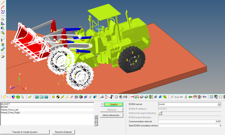
図 1. The user-interface for creating an instance of the MotionSolve-EDEM interaction
Build Model using EDEM Subsystem
The EDEM subsystem tool defines the co-simulation settings between MotionSolve and EDEM. Within the tool, you can:- Transfer graphics (for rigid and flexible bodies) from MotionView into EDEM.
- Transfer and set up tire geometry to model a flexible tire (from Pratt-Miller) in EDEM.
- Choose if EDEM runs locally or on a separate server.
- Define the communication parameters if EDEM runs on a separate server.
- Define simulation settings, such as the communication interval and simulation start time of EDEM.
From HyperWorks v2020, the interface is supported on Windows as well as Linux platforms. The interface can be used in cross-platform scenarios (HyperWorks on Windows and EDEM on Linux or vice-versa).
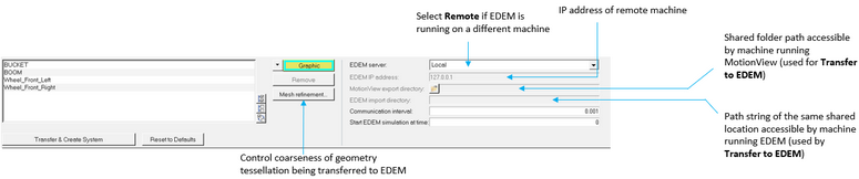
図 2. EDEM Subsystem Panel
- Use the collector to pick the graphics/body/AutoTire that will interact with the bulk
material in EDEM. When selecting using the Body collector, all valid graphics associated
with the body will be selected. Graphics of type Box, Cylinder, Sphere, Ellispoid,
CADGraphics, FileGraphics can be selected from the graphics area.
- Use the Body collector to select a flex body (CMS).
- AutoTire can be used to transfer a Pratt-Miller flexible tire. Refer to the AutoTire - Auto Entity documentation to learn more about setting up a flexible tire for co-simulation with EDEM.
ヒント: Use the Select a Graphic/Body dialog to pick multiple graphics simultaneously (double click on the collector to display this dialog).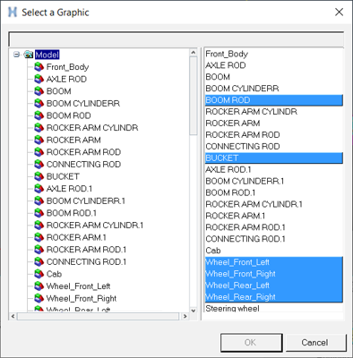
図 3. Select a Graphic Dialog注:- This functionality currently supports the following graphics: Box, CADGraphic, Cylinder, Ellipsoid, File (mesh-based graphics such as H3D/OBJ) and Sphere. Any other type of graphics selected using the Advanced Graphics selector dialog will not be used and a warning message will be displayed.
- Selected graphics that have no bodies assigned will be highlighted in red in the list. Such graphics should be removed from the list before transferring the geometry to EDEM or creating the EDEM system.
- To control the coarseness of the tessellation of the graphics (CADGraphics and
Primitives) that go into EDEM, click the Mesh Refinement
button.
Maximum facet width ratio Maximum width of elements in meters. Curve chord tolerance factor Tolerance factor that controls chordal deviation along curved edges. Surface plane tolerance factor Tolerance factor that controls surface deviation along curved surfaces. - Select the EDEM server:
- Local if EDEM are running on the same local machine as MotionView and MotionSolve.
- Remote if EDEM is running on a different machine.
- EDEM IP address - Specify the IP address of the machine where EDEM application is running. Default is set to 127.0.0.1 which refers to the local machine.
- MotionView Export directory – This is applicable only for transferring geometry to EDEM on a remote server. Select a shared directory which is accessible by both machines. MotionView will use this directory as a temporary location to transfer the geometry.
- EDEM Import directory – Path string of the same shared directory as above but as recognized by the machine running EDEM.
- Specify the communication interval between MotionSolve and EDEM.
- To transfer geometry to EDEM and create the EDEM system in MotionView, with the EDEM GUI and coupling server turned ON
 , click on Transfer and Create System.
A system is added to the MotionView model that contains the
requisite entities for MotionSolve’s coupling with
EDEM.注: With version 2022, the names of components in EDEM match the body names in MotionView. In previous versions, the names for the components in EDEM are component_0000, component_0001, and so on. For flexible bodies, the naming convention is flex_component_0000, and so on. The naming sequence matches the sequence of the graphic selection in the tool.
, click on Transfer and Create System.
A system is added to the MotionView model that contains the
requisite entities for MotionSolve’s coupling with
EDEM.注: With version 2022, the names of components in EDEM match the body names in MotionView. In previous versions, the names for the components in EDEM are component_0000, component_0001, and so on. For flexible bodies, the naming convention is flex_component_0000, and so on. The naming sequence matches the sequence of the graphic selection in the tool. - Start EDEM simulation at time - Enter a time at which the EDEM simulation is starting. The coupling between MotionSolve and EDEM will be established once MotionSolve reaches the specified time. Default is 0.0.
-
注: To change the IP address of the machine, the communication interval, or Start EDEM simulation at time after the system is created, use the data set 'DataSet_1' within the system.
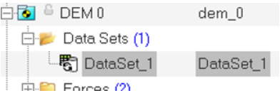
図 4. Data Set within the EDEM System
The model is now ready for co-simulation with EDEM.
Analyze Model
Once the model is defined, the solution process is identical to performing a “MotionSolve-only” simulation.
Use the Run panel in MotionView/MotionSolve to start the simulation. MotionView will launch MotionSolve.
MotionSolve will connect to EDEM (coupling server in EDEM should be ON) in the specified machine as a sub-process and start the communication. From here on, no additional user intervention is required to analyze the system.
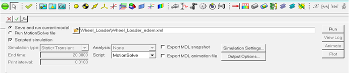
図 5. The user-interface for running a MotionSolve + EDEM simulation
Review Results
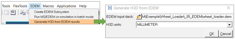
図 6.
- Use the Animate button in the MotionView Run panel to load the MotionSolve H3D into a HyperView window.
- Overlay the EDEM H3D in HyperView using the Overlay option in the Load Model and Results panel to visualize the entire system in one environment.
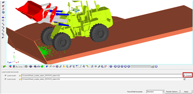
図 7. The user-interface for overlaying a MotionSolve + EDEM simulation result
Known Limitations
- MotionSolve supports up to 1024 rigid components to interact with EDEM.
- Multiple instances of EDEM coupling is not supported.
- NLFE Bodies are not supported.
- Certain graphics, when transferred to EDEM, may appear un-merged as several components. Use the “Merge Geometry” tool in EDEM to merge them into one component.
- Save/Load in MotionSolve, in conjunction with corresponding operations in EDEM, is not supported.
- Quasi-static and Linear analysis are not supported with this connection.
- On Windows if Microsoft C++ 2010 SP1 Redistributable Package (x64) is not available, then the co-simulation will fail with an error "Failed to load edem.dll".
See Also