OS-T: 5000 2D Shape Optimization of a Cantilever Beam
In this tutorial you will perform a shape optimization on a cantilever beam modeled
with shell elements.
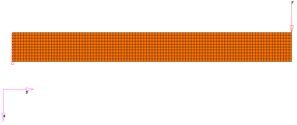
You will use a structural model with loads and constraints. The deflection at the
lower right corner should be limited to 3mm. The optimal design would use as little
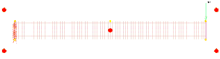
material as possible. Figure 1. Cantilever Beam, Structural Model
The structural model is loaded into HyperMesh and is used
to generate and run a shape optimization of the cantilever beam. Shape perturbation
vectors are generated using HyperMorph, which is
accessed, through the HyperMesh interface. The OptiStruct software determines the optimal shape. The results
are then reviewed in HyperView.
The optimization problem for this tutorial is stated as:
Objective
Minimize volume.
Constraints
Given maximum nodal displacement at the end of the beam < 3.0
mm.
Design Variables
Shape variables defined with HyperMorph.
Launch HyperMesh and Set the OptiStruct User Profile
Launch HyperMesh.
The User Profile dialog opens.
Select OptiStruct and click
OK.
This loads the user profile. It includes the appropriate template, macro
menu, and import reader, paring down the functionality of HyperMesh to what is relevant for generating models for
OptiStruct.
Open the Model
Click File > Open > Model.
Select the beamshape.hm file you saved to
your working directory from the optistruct.zip file. Refer
to Access the Model Files.
Click Open.
The beamshape.hm database is loaded
into the current HyperMesh session, replacing any
existing data.
Set Up the Optimization
Create Shapes using HyperMorph
In this step you will use HyperMorph to create
shapes.
From the Analysis page, click the optimization
panel.
Click the HyperMorph panel.
Create domain handles.
Click the domains panel.
Select the create subpanel.
Switch from global domains to auto functions and
keep the default settings.
Click generate.
Click return to return to the HyperMorph panel.
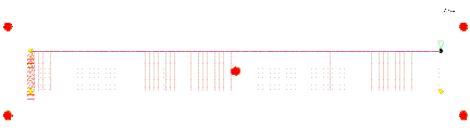
A number of domains and handles are created which will enable us to morph the
shape of the beam.
There are two types of handles: global handles, which are represented by
larger red balls; and local handles, which are represented by smaller yellow
balls. Only local handles will be covered in this tutorial.
Move handles.
Select the morph panel.
Select the move handles subpanel.
Switch interactive to move to node.
Using the handles selector, select the top right local handle (where
the force is applied).
Figure 2.
Using the nodes selector, select the node in the middle of the
right-hand side of the beam.
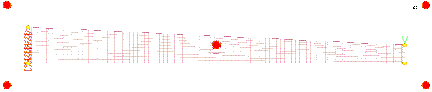
The beam changes shape, so that the handle you selected moved to the
location of the node you selected. Notice how the mesh adjusted to this change
in shape. Figure 3. Morphed Shape 1
Save the shape.
Select the save shape subpanel.
In the shape= field, enter shape1.
Click the color button to select a new color for the shape
vectors.
Under shape=, set the toggle to as node
perturbations.
Click save.
Click Yes.
This shape has been saved and can be associated with a design variable
later.
Click undo all.
The model returns to the original shape.
Click return to return to the HyperMorph panel.
Create handles.
Select the handles panel.
Select the create subpanel.
In the name = field, enter aux1.
Using the domain selector, select the top edge domain.
Tip: To ensure that you select the top edge domain, hold
down the left mouse button and move the mouse over the top edge of
the beam until the edge is highlighted (white), then release the
mouse button.
Set the toggle to by nodes.
Using the nodes selector, select the node at the center of the top edge
of the beam.
Click create.
Click return to return to the HyperMorph panel.
A new handle, 'aux1', is created at the center of the top edge of the
beam. Figure 4.
Move the handles.
Click the morph panel.
Select the move handles subpanel.
Switch from move to nodes to interactive.
Using the handles selector, select the yellow handle you just
created.
A manipulator axis is created on the selected
handle.
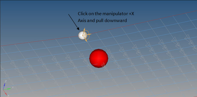
Left-click and hold down the mouse button on the manipulator axis
pointing in the positive X direction. While holding the mouse button
down, pull the selected axis in the positive X direction. Pull down
approximately until the center of the beam and release the mouse
button.
Note: The mesh morphs interactively as the handle moves
along the axis.
Figure 5. Morphed Shape 2
Set biasing.
Select the set biasing subpanel.
Using the handles selector, select aux1.
Select make retroactive.
Switch bias to screen edit.
The number 1.000 appears next to the handle 'aux1'.
Click the number and hold the mouse button down until the value reads
1.500.
Tip: If you move the mouse upwards the number increases, if
you move the mouse downwards the number decreases.
Click update.
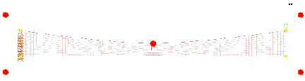
The curvature of the top edge has altered. Figure 6. Morphed Shape 3
Save the shape.
Select the save shape subpanel.
In the shape= field, enter shape2.
Click the color button to select a new color for the shape
vectors.
Under shape=, set the toggle to as node
perturbations.
Click save.
Click Yes if you wan to save perturbations for
nodes at global and morph volume handles.
This shape is now saved, later it can be associate to a design
variable.
Click undo all.
The model returns to its original shape.
Click return twice to return to the Optimization panel.
Create Shape Design Variables
Click the shape panel.
Select the desvar subpanel.
Switch the design variable option from single desvar to multiple
desvars.
Using the shapes selector, select shape1 and
shape2.
Click create.
Click return to return to the Optimization panel.
Two shape design variables are created using the shapes that were saved
earlier.
Create Optimization Responses
From the Analysis page, click optimization.
Click Responses.
Create the volume response, which defines the volume fraction of the design
space.
In the responses= field, enter vol.
Below response type, select volume.
Set regional selection to total and no
regionid.
Click create.
Create the displacement response.
In the response= field, enter disp.
Below response type, select static
displacement.
Click nodes > by id, then enter 1115 in the id=
field.
Set the displacement type to dof1.
dof1, dof2, dof3
Translation in the X, Y, and Z directions.
dof4, dof5, dof6
Rotation about the X, Y, and Z axes.
total disp
Resultant of the translational displacements in x, y, and z
directions.
total rotation
Resultant of the rotational displacements in x, y, and z
directions.
Click create.
Click return to go back to the Optimization panel.
Create Design Constraints
Click the dconstraints panel.
In the constraint= field, enter constr.
Click response = and select disp.
Check the box next to upper bound, then enter
3.0.
Using the loadsteps selector, select Load.
Click create.
Click return to go back to the Optimization panel.
Define the Objective Function
Click the objective panel.
Verify that min is selected.
Click response and select vol.
Click create.
Click return twice to exit the Optimization panel.
Define the SHAPE Card
Only displacement and stress results are available in the _s#.h3d file
by default. To obtain analysis results (displacement/stress/temperature) on top of a
shape change that was applied to the model in HyperView, a
SHAPE card needs to be defined.
From the Analysis page, click the control cards panel.
In the Card Image dialog, click
SHAPE.
Set FORMAT to H3D.
Set TYPE to ALL.
Set OPTION to ALL.
Click return twice to go back to the main menu.
Run the Optimization
From the Analysis page, click OptiStruct.
Click save as.
In the Save As dialog, specify location to write the
OptiStruct model file and enter
beamshape for filename.
For OptiStruct input decks,
.fem is the recommended extension.
Click Save.
The input file field displays the filename and location specified in the
Save As dialog.
Set the export options toggle to all.
Set the run options toggle to optimization.
Set the memory options toggle to memory default.
Click OptiStruct to run the optimization.
The following message appears in the window at the completion of the
job:
OPTIMIZATION HAS CONVERGED.
FEASIBLE DESIGN (ALL CONSTRAINTS SATISFIED).
OptiStruct also reports error messages if any exist. The
file beamshape.out can be opened in a
text editor to find details regarding any errors. This file is written to the
same directory as the .fem file.
Click Close.
View the Results
View the Shape Results
From the OptiStruct panel, click HyperView.
HyperView launches within the HyperMesh Desktop and loads beamshape_des.h3d on page 1 and beamshape_s2.h3d opens on page 2.
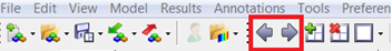
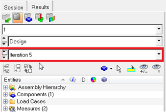
Use the navigations buttons to navigate to Design History on page 1.
Figure 7.
In the Results Browser, select the iteration.
Figure 8.
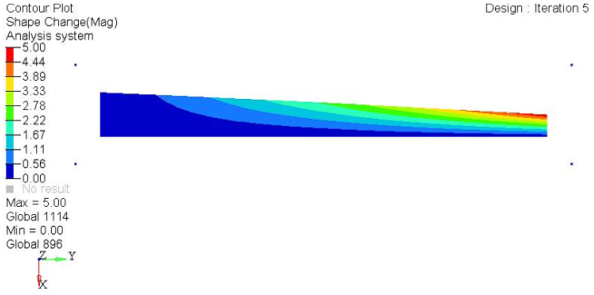
On the Results toolbar, click
to open the Contour panel.
Set the Result type: to Shape change (v) and
Mag.
Click Apply.
Shape optimization results are applied to the model. Figure 9.
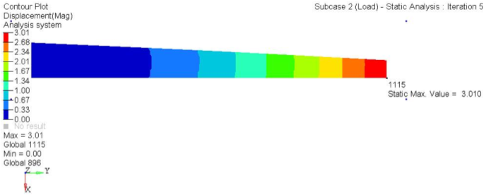
View a Contour Plot of the Displacement
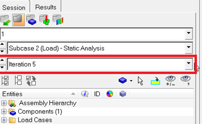
In the top, right of the application use the navigation buttons to move to page
2.
In the Results Browser, select the last iteration.
Figure 10.
On the Results toolbar, open the Deformed panel.
Set the Result type: to Shape Change (v).
Click Apply.
The optimized shape of the beam displays.
On the Results toolbar, click
to open the Contour panel.
Set the Result type: to Displacement (v) and
Mag.
Click Apply.
On the Annotations toolbar, click to open the Measures panel.
Select Static MinMax Result.
Node 1115 has a displacement which is within the constraint value. Figure 11.
 to open the Contour panel.
 to open the Measures panel.