OS-T: 5060 3D Model using the Free-shape Method with Manufacturing Constraints

In this tutorial you will perform a shape optimization on a solid model using the free-shape optimization method along with manufacturing constraints, such as symmetry and mesh barrier constraints. The objective of this optimization is to reduce the stress by changing the geometry of the model.


frshape_pic1
Figure 1.

Launch HyperMesh and Set the OptiStruct User Profile

  1. Launch HyperMesh.
    The User Profile dialog opens.
  2. Select OptiStruct and click OK.
    This loads the user profile. It includes the appropriate template, macro menu, and import reader, paring down the functionality of HyperMesh to what is relevant for generating models for OptiStruct.

Open the Model

  1. Click File > Open > Model.
  2. Select the freeshape3D_mfg.hm file you saved to your working directory from the optistruct.zip file. Refer to Access the Model Files.
  3. Click Open.
    The freeshape3D_mfg.hm database is loaded into the current HyperMesh session, replacing any existing data.

Set Up the Optimization

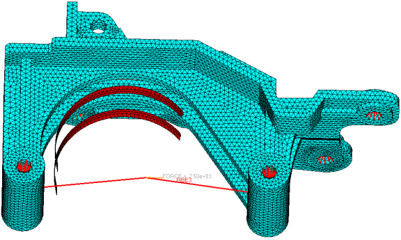
Create Free-shape Design Variables

  1. From the Analysis page, click the optimization panel.
  2. Click the free shape panel.
  3. Create the design variable, shape.
    1. Select the create subpanel.
    2. In the desvar= field, enter shape.
    3. Click nodes > by sets.
    4. Select shape_nodes, then click select.
    5. Click create.

    frshape_pic2
    Figure 2. Free-shape Design Space
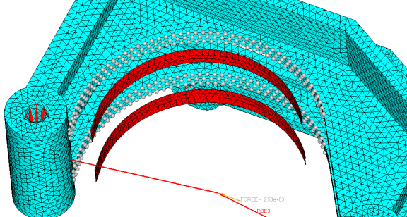
  4. Update the parameters for the shape design variable.
    1. Select the parameters subpanel.
    2. Set the direction to grow.
    3. In the mvfactor= field, enter 0.5.
    4. In the nsmooth= field, enter 10.
    5. Click update.

    5060_paramaters_sub
    Figure 3.
  5. Click return twice to exit the panel.

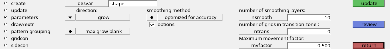
Convert Shell Elements to Create Barrier Mesh Face

  1. From the 2D page, click the elem types panel.
  2. Click elemsby collector.
  3. Select barrier, then click select.
  4. Select the 2D & 3D subpanel.
  5. In the tria3 field, click CTRIA3 and select BMFACE.
  6. In the quad4 field, click CQUAD4 and select BMFACE.
  7. Click update.

Define the 1-Plane Symmetry Constraint

The manufacturing constraint options for free-shape are: (Draw direction constraint, Extrusion constraint, Pattern grouping: 1-plane symmetry constraint, Maximum growing/shrinking distance control, Side constraint, and Mesh barrier constraint).
  1. From the Analysis page, click the optimization panel.
  2. Click the free shape panel.
  3. In the desvar= field, enter shape.
  4. Select the pattern grouping subpanel.
  5. Select pattern type to 1-pln sym.
    The 1-plane symmetry constraints in free-shape will produce symmetric designs regardless of the initial mesh, boundary conditions or loads. The plane of symmetry is defined by specifying the anchor and the first nodes. The plane of symmetry will then be perpendicular to the vector from the anchor node to the first node and pass through the anchor node.
  6. Click anchor node and enter 1 in the id= field.
    The node with the ID of 1 is selected.
  7. Click first node and enter 2 in the id= field.
    The node with the ID of 2 is selected.
  8. Click update to update the design variables.

frshape_pic3
Figure 4. Defining 1-plane Symmetry

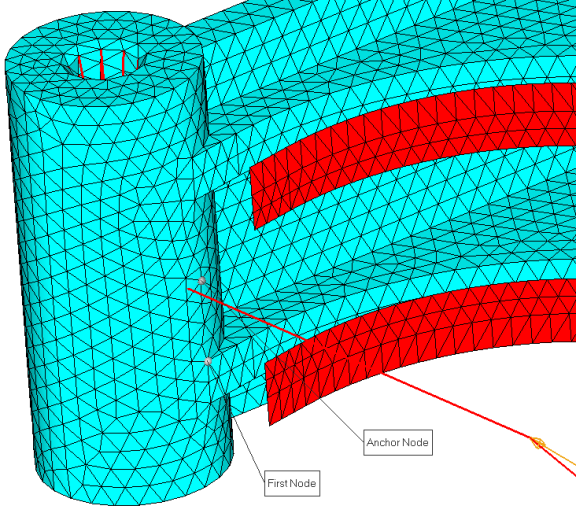
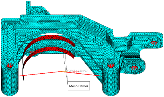
Define the Mesh Barrier Constraint

For this exercise, the mesh barrier was already created and the component name is barrier.
A mesh barrier constraint allows control on the total deformation extent of a design boundary/surface; mesh barrier will constrain the design boundary/surface to deform within the restricted design space and never penetrate the barrier.

The barrier should be constructed by shell elements with the smallest number of elements possible.

  1. In the free shape panel, click the sidecon subpanel.
  2. Click desvar = and select shape.
  3. Next to Barrier mesh, click component= and select barrier.
  4. Click update.
  5. Click return to go back to the main menu.

frshape_pic4
Figure 5. Mesh Barrier Component

Create Optimization Responses

  1. From the Analysis page, click optimization.
  2. Click Responses.
  3. Create the mass response, which is defined for the total volume of the model.
    1. In the responses= field, enter mass.
    2. Below response type, select mass.
    3. Set regional selection to total and no regionid.
    4. Click create.
  4. Create a static stress response.
    1. In the response= field, enter Stress.
    2. Set the response type to static stress.
    3. Set the entity selector to elems, then click elems > by sets and select stress.
    4. Set the response selector to von mises.
    5. Under von mises, select both surfaces.
    6. Click create.
  5. Click return to go back to the Optimization panel.

Create Design Constraints

  1. Click the dconstraints panel.
  2. In the constraint= field, enter stress.
  3. Click response = and select stress.
  4. Check the box next to upper bound, then enter 62.
  5. Using the loadsteps selector, select ls2.
  6. Click create.
  7. Click return to go back to the Optimization panel.

Define the Objective Function

  1. Click the objective panel.
  2. Verify that min is selected.
  3. Click response and select Mass.
  4. Click create.
  5. Click return twice to exit the Optimization panel.

Define the SHAPE Card

Only displacement and stress results are available in the _s#.h3d file by default. To obtain analysis results (displacement/stress/temperature) on top of a shape change that was applied to the model in HyperView, a SHAPE card needs to be defined.
  1. From the Analysis page, click the control cards panel.
  2. In the Card Image dialog, click SHAPE.
  3. Set FORMAT to H3D.
  4. Set TYPE to ALL.
  5. Set OPTION to ALL.
  6. Click return twice to go back to the main menu.

Run the Optimization

  1. From the Analysis page, click OptiStruct.
  2. Click save as.
  3. In the Save As dialog, specify location to write the OptiStruct model file and enter freeshape3d_mfgopt for filename.
    For OptiStruct input decks, .fem is the recommended extension.
  4. Click Save.
    The input file field displays the filename and location specified in the Save As dialog.
  5. Set the export options toggle to all.
  6. Set the run options toggle to optimization.
  7. Set the memory options toggle to memory default.
  8. Click OptiStruct to run the optimization.
    The following message appears in the window at the completion of the job:
    OPTIMIZATION HAS CONVERGED.
    FEASIBLE DESIGN (ALL CONSTRAINTS SATISFIED).
    OptiStruct also reports error messages if any exist. The file freeshape3d_mfgopt.out can be opened in a text editor to find details regarding any errors. This file is written to the same directory as the .fem file.
  9. Click Close.

View the Results

View Shape Results

  1. From the OptiStruct panel, click HyperView.
    HyperView is launched and the freeshape3d_mfgopt_des.h3d file opens in page 1 and the freeshape3d_mfgopt_s4.h3d file opens in page 2.
  2. In the top, right of the application, click pageNext-24 to move to page 2
  3. In the Results Browser, select Iteration 14, which is the final iteration result.
  4. On the Results toolbar, click resultsDeformed-24 to open the Deformed panel.
  5. Set the Result type: to Shape change(v).
  6. Click Apply.
Shape optimization results are applied to the model.

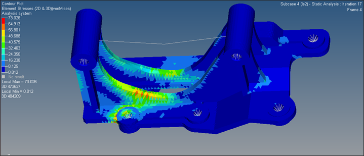
View a Contour Plot of the Stress

  1. On the Results toolbar, click resultsContour-16 to open the Contour panel.
  2. Set the Result type to Element Stresses (2D & 3D) (t).
  3. Set the stress type to von Mises.
  4. Under selection, set the selector to Elements.
  5. Click Elements > By set, then select stress.
  6. Click Add and close.
  7. Click Apply.

5060_final_4_7
Figure 6. von Mises stress contour on the final shape