OS-E: 2020 Solid Control Arm
Topography optimization has applications beyond creating beads in shell surfaces. Since the basic topography approach can be applied to any model containing large fields of shape variables, it lends itself to solid model applications.
Model Files
Refer to Access the Model Files to download the required model file(s).
The model file used in this example includes:
controlarm.fem
Model Description
The following example demonstrates how topography can be used in conjunction with user-defined shape variables to do global shape optimization of a solid part. All optimization set up is done using the Optimization panel and its subpanels in HyperMesh.
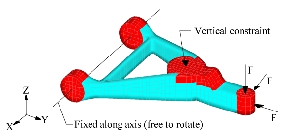
Figure 1. Loads and Constraints for Solid Control Arm
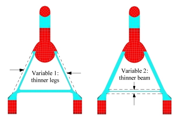
Figure 2. Shape Variables Controlling the Thickness and Height of the Control Arm Legs
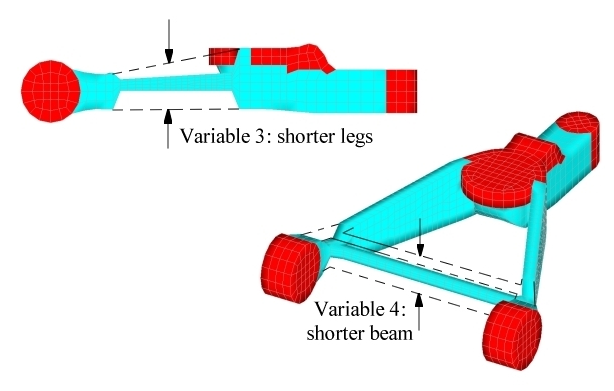
Figure 3. Shape Variables Controlling the Thickness and Height of the Control Arm Rear Beam
Topography optimization will divide these shape variables into smaller variables that control the height and thickness of sections of each leg. The type of pattern grouping selected for each variable is used to control the way that the variables get divided. Pattern grouping enhances the ability of topography optimization to affect the shape of solid models. Without pattern grouping, the distance that a grid is allowed to move must be less than the distance to the neighboring grid or else the elements will get turned inside out. With pattern grouping, the movement of several grids can be linked together so that those grids can move far beyond their original positions while still maintaining a reasonable element mesh (as demonstrated in this example problem).
Linear pattern grouping is applied to the first variable which links the movement of all of the grids through the thickness of both legs together. This allows the thickness of the legs to change at many points across the sides of the legs, which gives OptiStruct a high degree of flexibility in influencing their shape without causing problems with the finite element mesh.
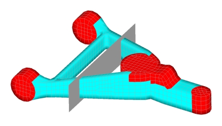
Figure 4. Pattern Grouping Plane for Variable #2
Figure 4 shows the variables created from the planar pattern grouping option. Figure 4 only shows the deflections of the centers of the variables. Because of the way that topography optimization works, if all three variables were fully deflected, the legs of the control arm would be uniformly at the minimum height.
| (1) | (2) | (3) | (4) | (5) | (6) | (7) | (8) | (9) | (10) |
|---|---|---|---|---|---|---|---|---|---|
| DTPG | 8 | DVGRID | 4 | ||||||
| + | 15.0 | 60.0 | NO | ||||||
| + | PATRN | 13 | 0.0 | 0.0 | 0.0 | 1.0 | 0.0 | 0.0 |
| (1) | (2) | (3) | (4) | (5) | (6) | (7) | (8) | (9) | (10) |
|---|---|---|---|---|---|---|---|---|---|
| DESVAR | 4 | DV004 | 0.0 | -1.5 | 1.0 |
Since shape variables are being assigned to topography, the height and the bounds in the DTPG card do not need to be defined, as they are controlled by the shape variable. Even if these values are defined, OptiStruct will ignore them.
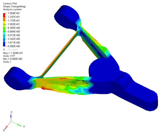
Figure 5. Optimized Control Arm using Topography and User-Defined Shape Variables
Results
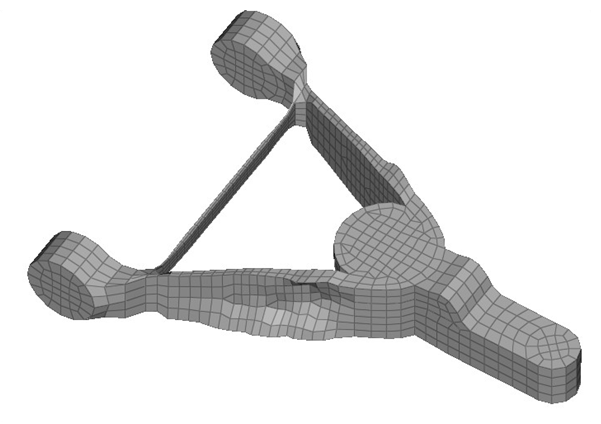
Figure 6. Finite Element Model of the OptiStruct Solution