OS-T: 8010 Trim Analysis of a Full Aircraft Model
This tutorial demonstrates trim analysis of a full aircraft model.
Preprocessing is done using Altair HyperMesh in the Nastran MSC User profile. A structural model with existing data is used as a base model and this tutorial demonstrates the creation of entities in the Aeroelasticity domain.
- Create Panel Mesh divisions (AEFACT)
- Create Panels (CAERO1)
- Ceate aeroelasticity box list (AELIST)
- Create interpolation splines (SPLINE1)
- Create rigid body motions for aeroelastic TRIM variables (AESTAT)
- Create aerodynamic control surfaces (AESURF)
- Define TRIM variables and link control surfaces (AELINK)
- Submit the job
- View the results
Launch HyperMesh and Set the Nastran MSC User Profile
-
In the drop-down list next to Aerospace, select NastranMSC.
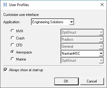
Figure 1. Aerospace (Nastran MSC) User Profile in HyperMesh
Open the Model and Aeroelasticity Browser
The Aeroelasticity Browser is useful for upcoming tasks in this tutorial.
-
Click Import.
The model database is loaded into the HyperMesh session.
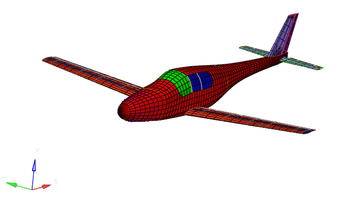
Figure 2. Base Structural Model of an Aircraft
Set Up the Model
This section is the main portion of this tutorial; the aeroelastic domain is defined. There are 18 entities total, as shown in Figure 3. The structural domain is shown in light grey.
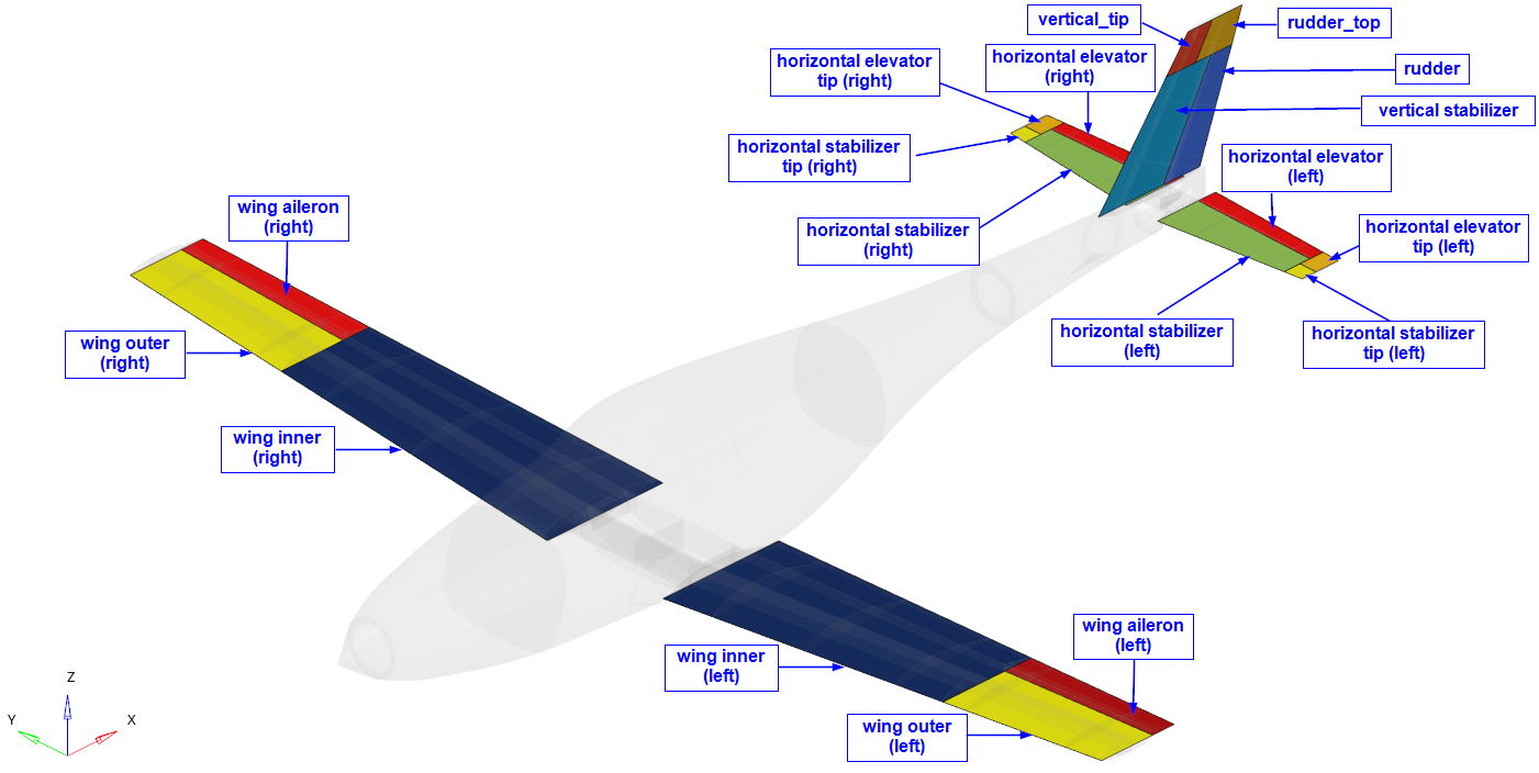
Figure 3. Entities of Aeroelastic Domain
Create AEROS Entry
In this step, basic/references parameters for the simulation are defined.
-
For REFS (Reference wing area), enter 12960.0.
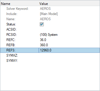
Figure 4. Definition of AEROS Entry
Create AEFACT Entries
The AEFACT entry is used to create tabular data of division points for the Aero panels; these panels are later referenced in the CAERO1 entry.
-
For Num Factors, enter 6.
A Data D row and table icon
 appear in the browser.
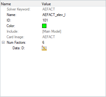
Figure 5. Definition of AEFACT Entry -
Click .
Create Aeroelasticity Panels
The CAERO1 entry is used to create aeroelasticity panel mesh in the base structure model. The AEFACT entries are used to create divisions in the panel mesh along the chord and span directions.
-
In the panel mesh utility, for Points 1-4, select
nodes.
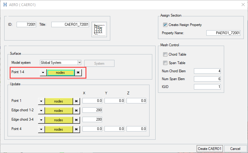
Figure 6. Nodes Selection in CAERO1 Definition -
Select the end points of the CAERO1 panel mesh so that node
1 and node 4 are along the span direction and node 1 and 2 are along the chord
direction. For more information, refer to CAERO1.
Figure 7 shows the correct selection order.
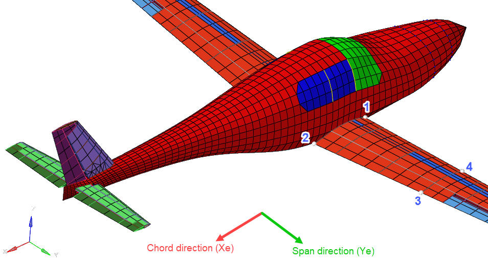
Figure 7. Selection Order of Nodes for CAERO1 Definition -
Select the AEFACT entry along the chord and span.
- In the panel mesh utility, click the Chord Table check box.
- Click AEFACT Chord.
- In the pop-up, select the corresponding AEFACT entry.
- Similarly, click the Span Table check box to select an AEFACT entry for span.
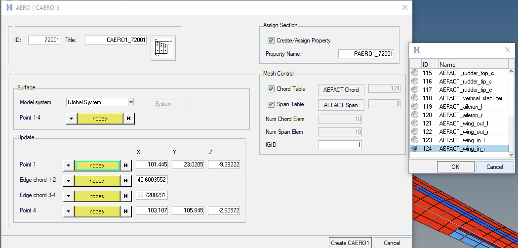
Figure 8. Definition of Chord and Span Tables in CAERO1 -
Repeat the above process using Figure 9 as a reference for point selection.
The structural domain is greyed out for better visibility.
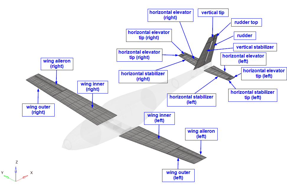
Figure 9. CAERO1 Definitions for Different Parts of the Aircraft
Create Aeroelasticity Box Lists
The AELIST entry is used to create lists of aeroelasticity boxes from the panel mesh (CAERO1).
-
When selection is finished, click proceed.
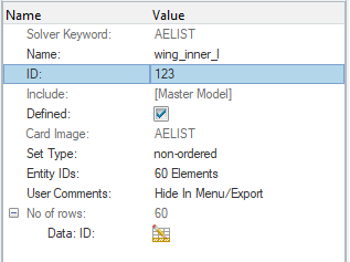
Figure 10. AELIST Definition -
Use this process to create AELIST entries for each of the
CAERO1 collectors.
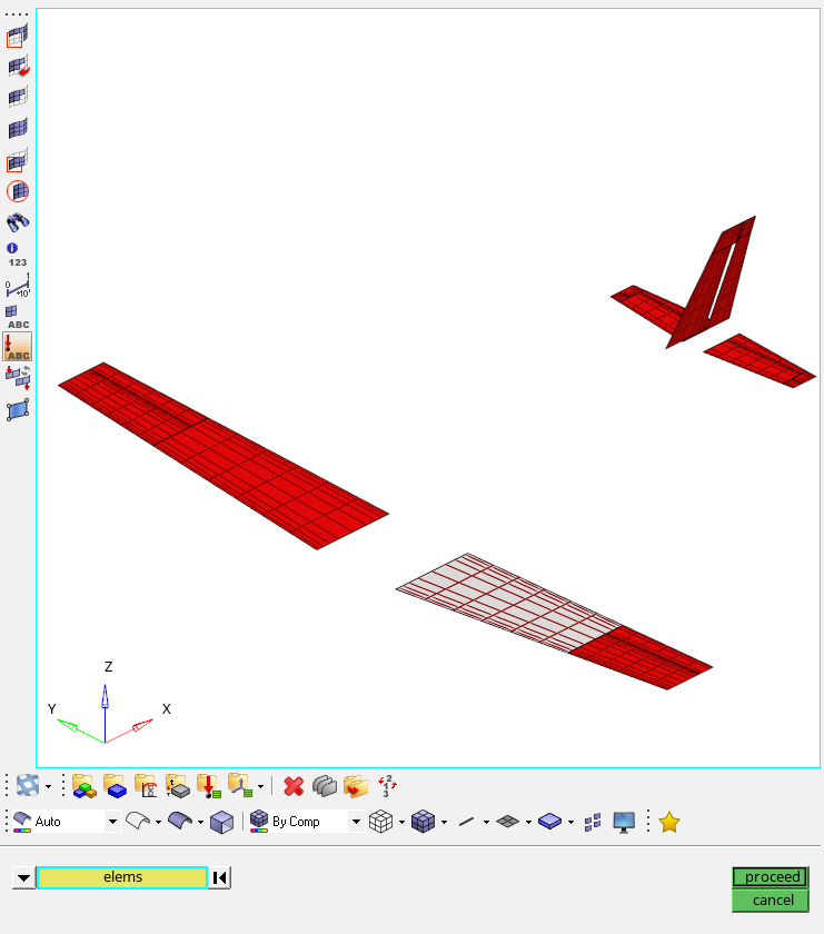
Figure 11. Selection of Elements for Each AELIST
Create Interpolation SPLINES
In this step, SPLINE1 entries are created for interpolating motion and/or forces between the aeroelastic and structural domains. Each SPLINE1 entry is reference to an AELIST set (aeroelastic domain), a node set (structural domain) and the corresponding CAERO1 entry. 18 SPLINE1 entries are created for each of the 18 entities in the aeroelastic domain. The node set for the structural domain is already available in the base model.
-
Reference the AELIST.
-
In the dialog, select the corresponding AESTAT
entry.
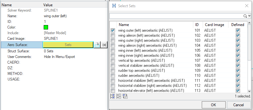
Figure 12. Reference AELIST in SPLINE1
-
In the dialog, select the corresponding AESTAT
entry.
-
Reference the node-set.
-
In the dialog, select the corresponding structural set already present
in the model.
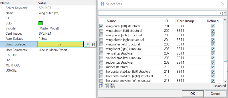
Figure 13. Reference SET1 in SPLINE1
-
In the dialog, select the corresponding structural set already present
in the model.
-
Reference the CAERO1.
-
In the dialog, select the corresponding CAERO1
entry.
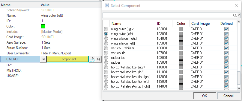
Figure 14. Reference CAERO1 in SPLINE1
-
In the dialog, select the corresponding CAERO1
entry.
-
Repeat this process for each of the 18 entities in the aeroelastic
domain.
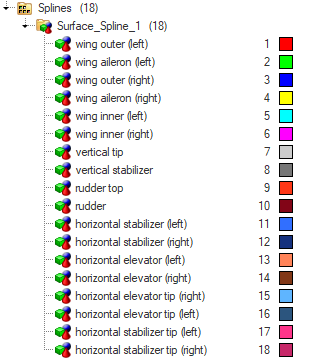
Figure 15. SPLINE1 Entities for the Model
Create AESTAT Entries
The AESTAT entry specifies rigid body motions which are used as trim variables in the aeroelastic analysis. This is later referenced in the TRIM Bulk Data Entry.
-
Use this process to create AESTAT entries for each DoF. For
more information, refer to AESTAT.
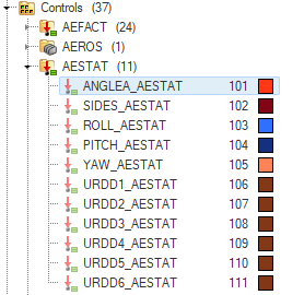
Figure 16. AESTAT Entries Defined in Model
Create AESURF Entries
In this step, the aerodynamic control surface is defined.
-
Create 5 AELIST sets corresponding to the entitites in Figure 17.
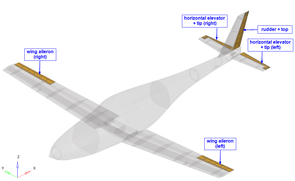
Figure 17. Additional AELIST for AESURF -
In the pop-up window, choose the AELIST corresponding to the
right wing alieron.
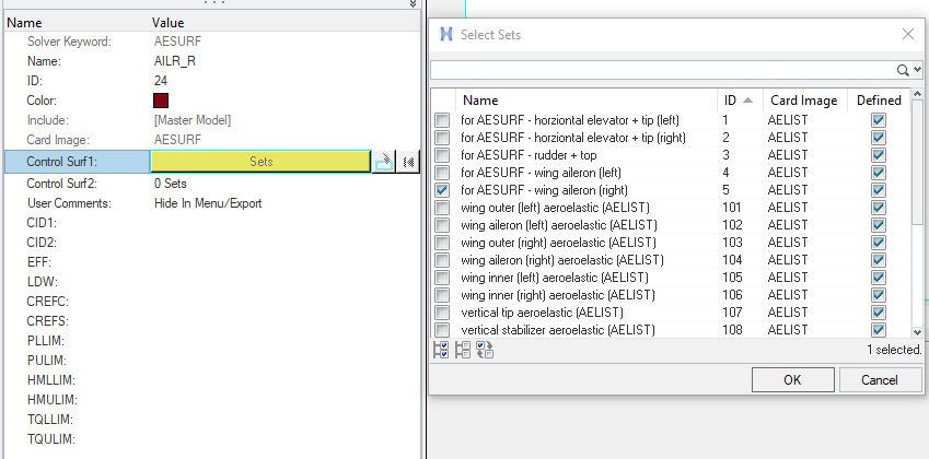
Figure 18. Select the AELIST for AESURF
Export the Input File and Add Aeroelastic Entities
In the following steps, certain entities which are not fully supported in HyperMesh are added to the input file manually using a text editor.
Export the Input File
-
In the Export browser, click
 .
.
-
Click Export.
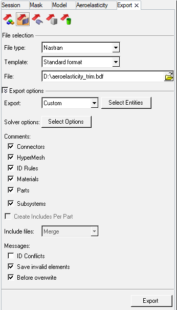
Figure 19. Export Input File from HyperMesh
Define TRIM Entry
In this step, the Mach number, Dynamic pressure, and constraint values for the aerodynamic trim variables are defined.
Define AELINK Entry
In this step, the AELINK entries are used to define relationships between the AESURF entries.
Define Aeroelastic Subcase Information Entries
- The TRIM Bulk Data Entry is referenced in the subcase.
- Aeroelastic output requests are added.
- Symmetry flags are added.
Perform Corrections to the Input File
Due to some HyperMesh export issues, the input file requires some manual correction. These issues will be addressed in future releases.
-
In SPLINE1, check that BOX1 ID and BOX2 ID match the upper
and lower bounds of the corresponding CAERO1 entries.
- If the bounds are incorrect, review the CAERO1 entries and correct them in SPLINE1.
-
In SPLINE1 verify that BOX1 ID < BOX2 ID.
- If the values are incorrect, swap them accordingly.
- Change the value of EFF in AESURF from 0.0 to 0.1.
Submit the Job
-
For Input file, use
 to browse your working directory for the desired
file.
to browse your working directory for the desired
file.
-
For Options, click
 .
.
- In the Select Solver Options dialog, click the -nt check box.
- Enter 8 for the argument.
- Click OK.
- Click the -out check box.
-
Click Run.
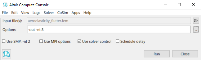
Figure 20. Altair Compute ConsoleIf the job is successful, the new results files should be in the working directory. If any errors are present, look in the aeroelasticity_trim.out file for error messages that could help debug the input deck.
View the Contour Plot
-
After you receive the analysis completion message, click
Results.
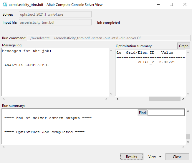
Figure 21. Altair Compute Console Solver View Window -
In HyperView, click the Contour panel button
 .
.
-
Click Apply.
The resulting contour represents the displacement field for the aeroelastic trim analysis.
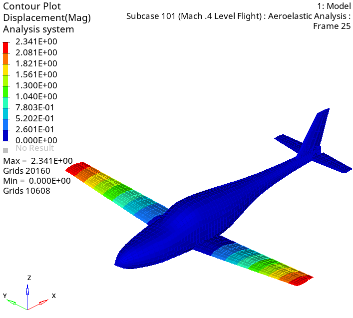
Figure 22. Displacement Contour Plot of the Aircraft