Lattice Optimization
Lattice optimization fills your design space with an optimized lattice structure. It is essentially a traditional topology optimization where solid elements are replaced with lattice beams.
Use the Run Optimization tool to set up and run a lattice optimization.
- Lattice optimization only works on solids, and design spaces have to be separated with non-design space.
- When running a lattice optimization, you can maximize stiffness or minimize mass as your optimization objective, with all of the same optimization constraints available as with topology optimization.
- The results of a lattice optimization are shown as analysis results rather than optimization results. Lattice results appear as alternatives in the Model Browser and can be exported as an STL using the File>Save As command.
 Figure 1. Design Space
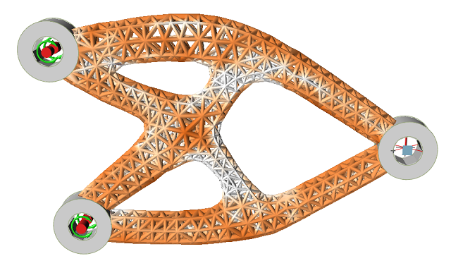
 Figure 2. Optimized Shape
Running a Lattice Optimization
When running a lattice optimization, choosing minimize mass as the optimization objective, with explicitly defined stress and displacement constraints, helps ensure a robust optimization problem definition with clearly defined targets. If the maximize stiffness objective is selected, a stress constraint is used but displacement constraints are not required. In this case, a high mass target typically yields the best results.
A lattice structure occupying the same design space as a solid structure will be less stiff and have higher stresses. For this reason, it is often necessary to set your design requirements more conservatively than you normally would for a traditional topology optimization. It is not uncommon for displacements and stresses to be five to ten times greater in a lattice structure compared to that of a solid structure occupying the same region. As it is not always possible to have an accurate estimate of the degradation, it may be necessary to start the optimization with increasingly strict constraints before a desired result from the lattice optimization is obtained.
Lattice Dimensions
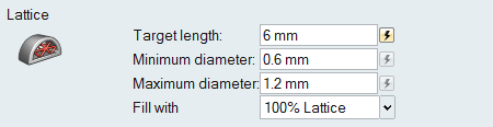
- Target length: The target length of a lattice beam.
- Minimum diameter: The minimum allowed diameter of a lattice beam.
- Maximum diameter: The maximum allowed diameter of a lattice beam.
The target length corresponds to the edge length of the parent solid element. When defining the minimum and maximum diameters of the lattice beams, both the practicalities of the geometry and the capabilities of the intended manufacturing process should be considered. With a length to diameter ratio of greater than 3, you start to produce a solid more voids rather than a true lattice structure.
Complete vs. Partial Lattice
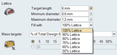
Selecting a percentage less than 100% will result in a structure that is a mix of solid and lattice elements. In general, the results of this approach are often less aesthetically pleasing, with jagged or unusual results. Selecting 100% will fully convert the design space to an optimized lattice. This approach typically produces intuitive, aesthetically pleasing results with clean transitions between design and non-design regions.
Lattice Properties
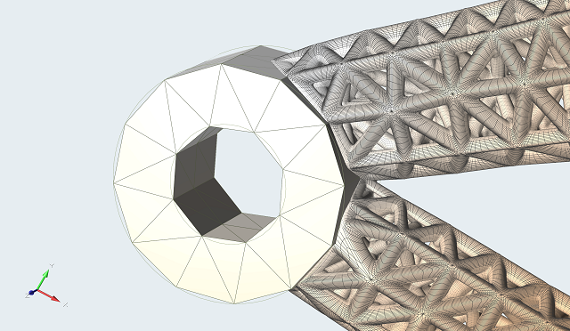 Figure 3. Lattice with Autocalculate Element Size On
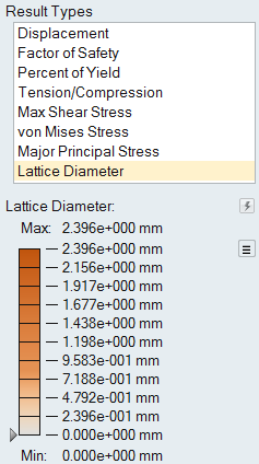
Lattice Diameter Result Type
Instead of the Shape Explorer, the Analysis Explorer is displayed at the end of a successful lattice optimization run.
Smooth Lattice
You can create radii between the lattice beams to display a "smooth lattice" using
the Show options on the Analysis explorer.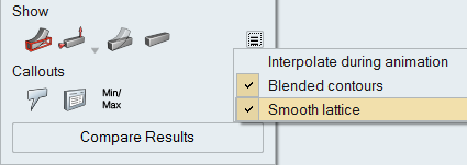
Click the ![]() button next to Show/Hide Contours icon and select
Smooth Lattice to create radii between the lattice
beams.
button next to Show/Hide Contours icon and select
Smooth Lattice to create radii between the lattice
beams.
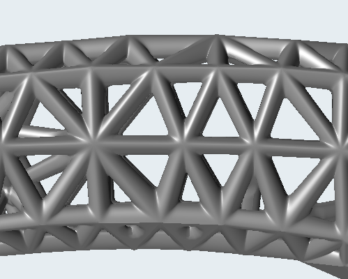
Figure 5. Smooth Lattice On
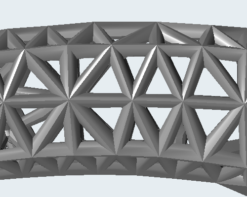 Figure 6. Smooth Lattice Off