CL Card
This card defines an arc consisting of wire segments.
On the Construct tab, in the Wires group,
click the ![]() Elliptic arc (CL) icon.
Elliptic arc (CL) icon.
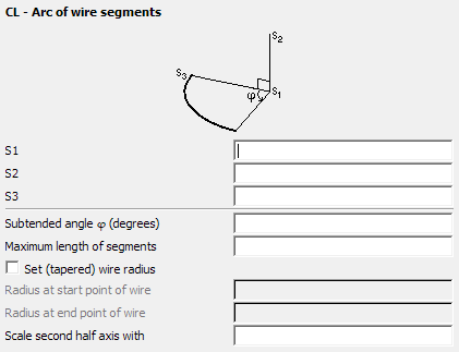
Figure 1. The CL - Arc of wire segments dialog.
Parameters:
- S1
- The centre point of the circle.
- S2
- A point perpendicular to the plane in which the circle lies and above its centre.
- S3
- The start point of the arc.
- Subtended angle
- The direction of the subtended angle, , is in the positive sense around the axis S1–S3. A negative value will create the arc in the opposite direction.
- Maximum length of segments
- The maximum length of the segments that make up the arc. If this field is left empty, the value specified with the IP card is used. This length is in m and is scaled by the SF card.
- Set (tapered) wire radius
- If checked, the radius set at the previous IP card is overridden for the current arc. This setting does not affect segments created after this card. Both radius values are in metres and are affected by the SF card scaling factor. If only the start radius is specified, the arc will have a constant wire radius.
- Radius at start point of wire
- The radius of the wire at the start point.
- Radius at end point of wire
- The radius of the wire at the end point.
- Scale second half axis with
- If this parameter is empty or is set to 1, a circular arc is created. If set to , an elliptical arc is created. Here gives the ratio of the two half axes, where is the distance S1–S3. It is not recommended to generate elliptical arcs with a CAD system if the elliptical arc has an extremely small or extremely large axial ratio as the distortion formulation used in PREFEKO may fail for such cases.
Often modelling the geometry of an arc requires shorter segments than those used for straight wires. Thus the maximum segment length specified with the IP card can be overridden along the arc by specifying a value in the Maximum length of segments text box.
The radius of the arc is given by the distance between the points S1 and S3.
Examples of CL card usage:
The meshes depicted in the two figures below are created with the CL card. The first figure shows the result of a wire arc with a uniform radius, and the second figure shows the result with an exaggerated taper specified.

Figure 2. Example of an arc with uniform wire radius created with a CL card.

Figure 3. Example of an arc with tapered wire radius created with the CL card.