PE Card
This card defines the unit cell for a periodic boundary condition (PBC) calculation. The phase change between cells is specified with the PP card.
On the Home tab, in the Planes / arrays
group, click the ![]() Periodic boundary
icon. From the drop-down list, click the
Periodic boundary
icon. From the drop-down list, click the ![]() Periodic boundary (PE) icon.
Periodic boundary (PE) icon.
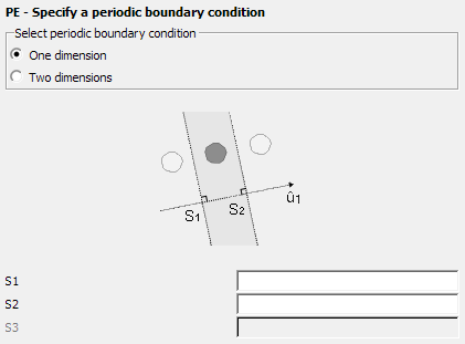
Figure 1. The PE - Specify a periodic boundary condition dialog - One dimension
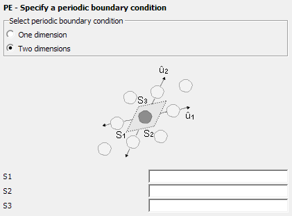
Figure 2. The PE - Specify a periodic boundary condition dialog - Two dimensions
Parameters:
- One dimension
- One dimensional periodicity is used when the unit cell is repeated along a line. The unit cell definition is displayed in the dialog above depicting the One dimension option.
- Two dimensions
- Two dimensional periodicity is used when the unit cell is repeated to form a surface. The unit cell definition is displayed in the dialog above depicting the Two dimensions option.
- S1
- Name of the point S1.
- S2
- Name of the point S2.
- S3
- Name of the point S3. (Only required for two dimensional periodicity.)
The lattice vectors ( and ) do not have to be orthogonal. Geometry may also cross the periodic boundary as long as it lines up with the geometry edge on the opposite side of the unit cell. These features allow a large number of problems to be solved.
The following restrictions apply for the current implementation of periodic boundary
conditions:
- PBC is not available in conjunction with volume equivalence principle (VEP).
- Triangles and wires are not allowed to cross, but are allowed to touch the cell boundary.
- PBC can be used with the free space Green’s function.
- PBC can only be used with MoM (both sequential and parallel), but not with the MLFMM, PO or UTD techniques.