Problem 5: Dynamic Analysis of Linkages in a Mechanism
Objective

Figure 1.
Entities Validated
- Rigid body
- Gear joint
Type of Analysis
- Dynamic
Reference
THEORY OF MACHINES AND MECHANISMS, Third Edition by John J. Dicker, Jr., Gordon R. Pennock, Joseph E. Shigley:110
Model Files
gear_joint_mechanism.mdl - MotionView Model
gear_joint_mechanism.xml - MotionSolve Deck
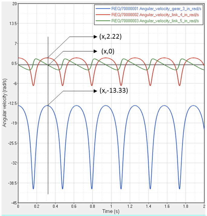
Graphical Results

Figure 2.
Result Comparison
| Output | Analytical | MotionSolve | % Error |
|---|---|---|---|
| Angular velocity of gear 3 (rad/s) | -13.33 | -13.33 | 0% |
| Angular velocity of link 4 (rad/s) | 2.22 | 2.22 | 0% |
Conclusion
MotionSolve results compare well with analytical results.