RD-HWX-T: 1060 Three Point Bending Model Setup
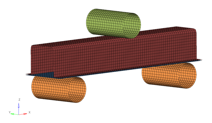
This tutorial demonstrates how to set up a 3-point bending model consisting of a head profile and a closing plate.

Figure 1.
- Step 1: Import Solverdeck
- Step 2: Check /BEGIN card
- Step 3: Define material
- Step 4: Assign material
- Step 5: Define property
- Step 6: Assign property
- Step 7: Create solid spotweld
- Step 8: Define failure /FAIL/CONNECT
- Step 9: Define rigid body
- Step 10: Create boundary condition
- Step 11: Create imposed velocity
- Step 12: Set contact
- Step 13: Define output (time history / anim)
- Step 14: Create Engine setup and export the model
- Step 15: Run the model and check the results in HyperView and HyperGraph
Model Description
- Material creation (with strain curve creation) and assignment:
- Elasto-plastic material /MAT/LAW36 (plastic):
- [Rho_I] Initial density = 7.85e-09 (ton/mm3)
- [nu] Poisson’s ratio = 0.29
- [E] Young’s modulus = 210000 (Mpa)
- Elasto-plastic material /MAT/LAW36 (plastic):
- UNITS: Length (mm), Time (s), Mass (t)
- Simulation time: [0 – 7.01E-02]
- Boundary Conditions: The supports are all fixed. An imposed velocity of 1000.0 mm/s is applied on the impactor.
- Model size: 370mm x 46.5mm x 159mm
Prerequisites
To run this simulation, you will need access to a licensed version of Radioss. You will need an internet connection to watch the video tutorials and download the files.