Tutorial: Adding a Chiller and Mold
See how the two halves of a reflectionally symmetric part solidify when a chiller is added to one side.
In this exercise, you will learn how to analyze the effect a chiller has on casting.
Model file is available in the tutorial_models folder in the installation directory in Program Files\Altair\2022.3\InspireCast2022.3\tutorial_models\chiller.x_b.
Import Geometry
-
Click Open Model on the Files icon and browse to the
tutorial model file in the installation directory, or drag-and-drop the file
into the modeling window.

Designate a Casting Part
Select casting geometries with the Cast Part tool.
Important: A cast part must be defined before performing any other
operation.
-
On the Cast Part icon, click Designate
Casting Part.

-
Left-click to select which candidate is a cast part.
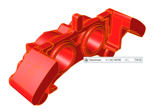
Parts are automatically detected and highlighted based on your cursor position. Since there is a single geometry the entire cast part will be automatically highlighted.The selected part is highlighted red.
-
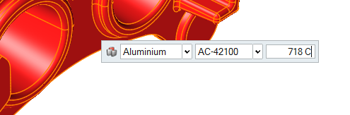
In the microdialog, select
Aluminum as the material and
AC-42100 as the alloy for the part.
Add a Chiller
-
Click the Components tool.

Click the Add/Edit Chiller tool in the secondary tool group.
-
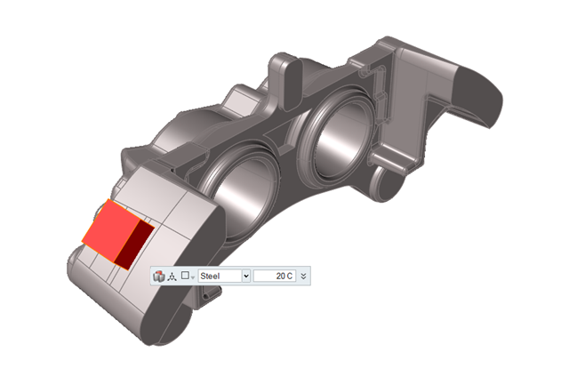
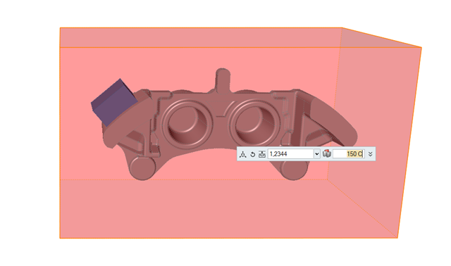
Click the surface of the part to create a chiller.
-
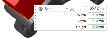
Select Steel and click
 to enter dimensions of 40 mm for
the Width, Depth, and
Height.
to enter dimensions of 40 mm for
the Width, Depth, and
Height.
Add a Mold
-
Click the Components tool.
Click the Add/Edit Mold tool in the secondary tool group.
-
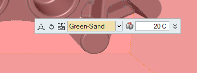
Select Green-Sand and enter 20 C.
Run Analysis
-
On the Analysis icon, click Run
Analysis.

-
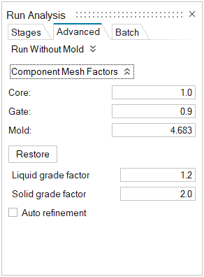
Select the Advanced tab to manually select mesh factors
for components like gate, mold, runner, riser, etc.
-
Select the Stages tab and click
Run.
Note: Once the simulation calculation is finished, a green flag will appear on the analyze icon.

Analyze Results
-
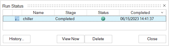
Click the green flag on the Analyze icon
Note: You can also select the results by clicking View Now in the Run Status window.
-
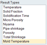
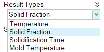
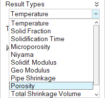
Click Mold Temperature under Result
Types.
-
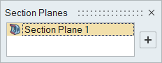
Click Add/Edit Section Cuts.
-
Select the Section Plane.
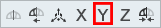
-
Click Align to Global Y Axis.
-
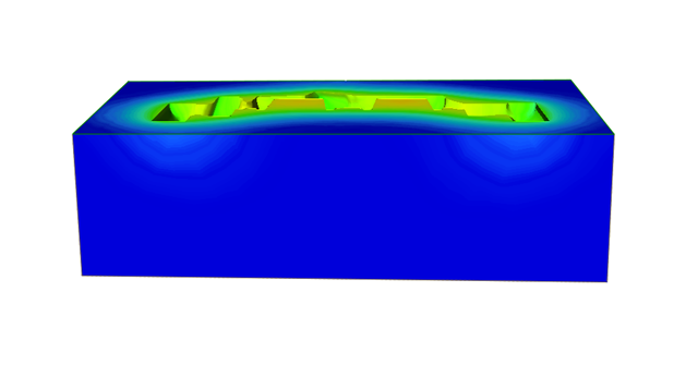
Click Play
to start the animation.

We can observe the mold temperature differences during the solidification evolution between both sides (with and without chiller).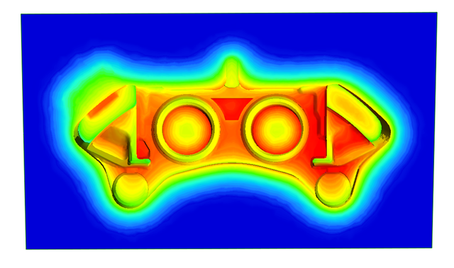
-
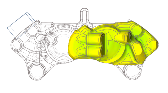
Click Solid Fraction under Result
Types.
-
Set the Solid Fraction percentage to
0.70.
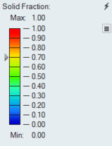
Note: The solid fraction value is set to 0.70 by default. In most cases, this corresponds to the value at which the liquid stops flowing. -
Click Play
to start the animation.
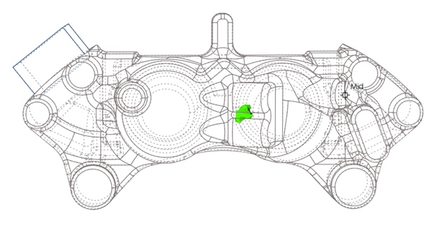
In the animation, solidified material (above 0.7) is transparent, while liquid material (below 0.7) is shown colored. Shrinkage porosity is more likely to occur in isolated areas.Notice how the final region to solidify is on the right side thanks to the effect of the chiller.
-
Click Demolding under Stage, then
click Porosity under Result
Types.
-
Set the percentage to 50%.
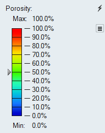
The effect of the chiller is keeping the left side free of porosity.