Technical Concepts
Details about the strengths of SnRD as a tool.
Capturing Squeak and Rattle Issues
Squeak and Rattle issues are always caused by relative displacement between two components which are mounted with or without any gap, and might interact for a short duration of time. This means, if there is no relative displacement, then there are no squeak and rattle issues.
- Acoustics method - Issues are captured using acoustical methods, and these captured sound quality will define the squeak and rattle issues.
- Laser Scanning Vibrometer - is an instrument for rapid non-contact measurement and imaging of vibration.
SnRD Methodology
The power of Virtual Simulation enables you to successfully, design and engineer innovative products for today’s competitive environment. The ability to analyze the multifaceted physical performance characteristics of a design, before any prototype is made can substantially increase productivity. Companies need robust simulation tools to efficiently overcome time, budget and quality constraints.
The development of the Squeak and Rattle Director is based on the above principle. This tool will help the CAE analysts in identifying the locations of squeak and rattle noises based on multiple risk analysis capabilities. Moreover, SnRD enables root cause analysis and diagnosis of the issues detected, enabling communication to other stakeholders, such as designers and manufacturing. The problem solving is the key in development cycle, therefore SnRD has been enhanced with Optimization setup as well, to guide you in proposing efficient design changes.
In order to capture the squeak and rattle issues in simulation, SnRD takes the Evaluation Line method, which focuses on the calculation and the evaluation of the relative displacement mathematically using Altair HyperWorks X. In order to bring the simulation approach as close as possible to the real test scenario, a random load in time is used as input signal and squeak & rattle issues are captured by calculating and evaluating the relative displacements.
- In the simulation approach, the critical areas can be in most cases represented by a 3D line in the FE model. This line will be created between two parts, in which one will be defined as master and the other as slave.
- Along the 3D line, node pairs are created with your defined spacing, with one node on master surface, the other on slave surface.
- The nodes are mesh independent and a local displacement coordinate systems for the analysis is assigned to each node pair.
- In order to capture the local gap or contact geometry, the local coordinate system at each node pair is aligned to the slave surface.
Evaluation Point:
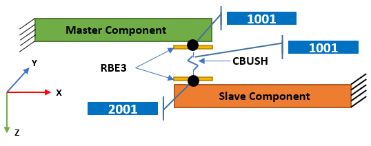
Figure 1.
Evaluation Line
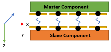
Figure 2.
The bigger challenge for squeak and rattle simulation is to correlate the calculated results to an audible squeak and rattle issue captured using physical methods.
The following sections provide more details about the strengths of SnRD as a tool and individual capabilities: