Extract Displacement Data
Extracts displacement data for user defined node set(s).
Extracting displacement data is useful for doing breakout modeling within a sub-modeling scheme.
After you define an element set with an associated node set, all appropriate displacements and rotations are extracted. Results can be output to load collectors for graphical review, a text summary table, and a formatted .csv file which can be loaded into traditional spreadsheet software packages.
-
From the menu bar, click Post > Free Body > Displacements.
The FBD Displacements tab opens.
-
In the .op2/.odb file field, specify the full path and
file name of the results file containing the displacement output for the current
model.
Once an results file is selected, loadstep names and IDs with displacement output are saved with the rest of the HyperMesh database for use with all FBD utilities. If a new results file is required, or if the original results file changes, you must load the new results file into the database, overwriting the previously selected one.
-
In the Loadsteps section, select which loadstep(s) to extract displacement
information.
Only loadsteps with displacement results from the currently selected results file display for selection. You can select multiple loadsteps by Ctrl-clicking or Shift-clicking. Filter buttons allow for additional selection control, including a namefilter that uses standard HyperMesh filtering syntax. The loadstep display can be switched between ID and Name (ID).
The ID option lists the loadsteps as "SUB-CASE #". The Name (ID) option lists the loadstep as "SUBTITLE - LABEL(ID)". If no SUBTITLE exists, only the LABEL is used. See the OptiStruct online reference guide for more information regarding SUBTITLE and LABEL loadstep information cards.
-
Select entities to extract displacement data from.
The entity selection section allows you to select and/or create the appropriate entities required to execute the FBD Displacements utility.
-
Use the Element Set selector to define the elements that contain the
nodes at which displacement data will be extracted.
The Set Browser utility on the Tools menu can be used to create the necessary element sets.
-
Use the Node Sets selector to define the nodes at which displacement
data will be extracted.
Only the nodes contained within the selected node set will be part of the extraction. If a node set is not selected, then all nodes within the element set are used.
-
To automatically finds the nodes attached to elements that are not
contained within the currently selected element set, select the
Auto find interface nodes checkbox.
This procedure selects the nodes interfacing with the remainder of the structure. You will be prompted to give the newly created node set a name. Additional nodes may be added to the node set once it is created by clicking the Node Setselector and picking additional nodes.
-
To automatically displays the entire model in transparency mode and
highlights the currently selected element and node sets, select the
Show Model checkbox.
This functionality allows you to verify which element and node sets are currently selected.
-
Use the Element Set selector to define the elements that contain the
nodes at which displacement data will be extracted.
-
Define Output options.
The Output options section contains various options to review and display results of FBD Displacement extractions.
-
Use the Coordinate Systems selector to determine the coordinate system
used to display the nodal coordinates (x,y,z) in the summary table and
.csv file output options. Displacement data
(Ux, Uy,…) is always output in the system that the results are stored
with in the results file format. Results coordinate system
transformations are not performed on displacement data.
The FBD Displacement utility extracts and applies the displacement and rotation results from the results file in the output coordinate system without any further coordinate system transformations. It is assumed that the output coordinate system assigned to each node in the HyperMesh database matches that used to run the analysis and generate the results file. Output coordinate systems are defined in HyperMesh by accessing the Systems panel. On the Setup menu, click Coordinate Systems, and toggle to the assign subpanel, select the required nodes and a coordinate system, and click Set Analysis. In OptiStruct and Nastran this operation sets the CD field on the GRID card(s). See the OptiStruct online reference guide for more information regarding the GRID bulk data card. If the output coordinate systems for each node in the HyperMesh database does not match those used to run the analysis then the extracted values will be incorrect. Situations when this behavior could occur include modification of nodal output system within HyperMesh without rerunning the analysis and/or loading a results file that does not match the currently loaded model.
If a coordinate system is not specified, the HyperMesh "base" system is used by default.
- In the Zero Tolerance field, enter the cut-off point below which a result quantity is considered zero. All calculations are done with float point precision and the zero tolerance value is only used for controlling the output of results to the various formats. The option helps to eliminate "relatively small" values from being output to the result formats. To maintain float precision the default is set to 1.0e-6, otherwise modify the value as desired.
-
To extract the specified displacement data and display it in organized
load collectors within HyperMesh for
graphical visualization within the model window5, select the
Create Load Collectors checkbox.
A single load collector, for the current element and node set, is created for each loadstep. The load collector name format is FBDD_E(#)_N(#)_S(#)_Disp. For example, FBDD_E(1)_N(1)_S(1)_Disp would be created for element set 1, node set 1 and loadstep 1. The loads in this load collector are created with the SPC load type. This collector can be referenced as the SPC in the loadstep panel.Tip: To choose a color for all created load collectors, click the Color button. This color can be modified later using either the interface or the FBD Results Manager utility
-
To create a load collector with the name "FBDD_E(#)_N(#)_S(#)_SPCD",
select the Create SPCD checkbox.
Loads in this collector are created with the SPCD load type. This collector can be referenced as the LOAD in the loadstep panel.
-
To output the results to a popup window for instant review, select the
Show summary checkbox.
The table contains information about the loadsteps, element and node set(s), and detailed displacement data at each node.
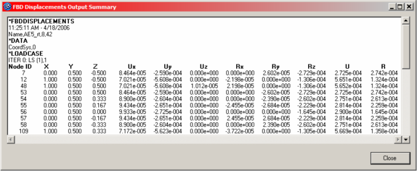
Figure 1. -
To create a .csv file that contains the same
information as the summary table, but in a comma-separated file, select
the Create .csv file checkbox, then select a new
file or an existing file.
If the data you are extracting already exists in the file, based on element set, node set and loadstep IDs, the existing block will be overwritten with the new data. If it does not exist, it will be appended to the end of the file.
In any case, you will be warned that the file already exists and asked if you want to replace it. Selecting yes will not overwrite the file; it will append/replace the data.
-
Use the Coordinate Systems selector to determine the coordinate system
used to display the nodal coordinates (x,y,z) in the summary table and
.csv file output options. Displacement data
(Ux, Uy,…) is always output in the system that the results are stored
with in the results file format. Results coordinate system
transformations are not performed on displacement data.
- Click Accept.