Review Grid Point Force Balance

The Grid Point Force Balance table is the data around which all FBD-Forces and Resultant Force and Moment utility calculations are performed.

See the OptiStruct online reference guide for more information regarding GPFORCE option cards.


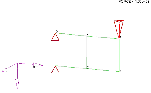
Figure 1. Sample Model used to Demonstrate Grid Point Force Calculations. This model consists of two elements, a fixed support on the left end, and a point load on the right end.
The complete GPFORCE table for the above cantilever beam model is presented below.
Note: For any given node within the GPFORCE table, several types of entries are possible depending on the forces acting at that node.
  • Applied forces and moments
  • SPC forces and moments
  • MPC forces and moments
  • Element forces and moments from elements attached to the node
  • Total summed values for each node, which in turn must sum to zero for the complete GPFORCE table.
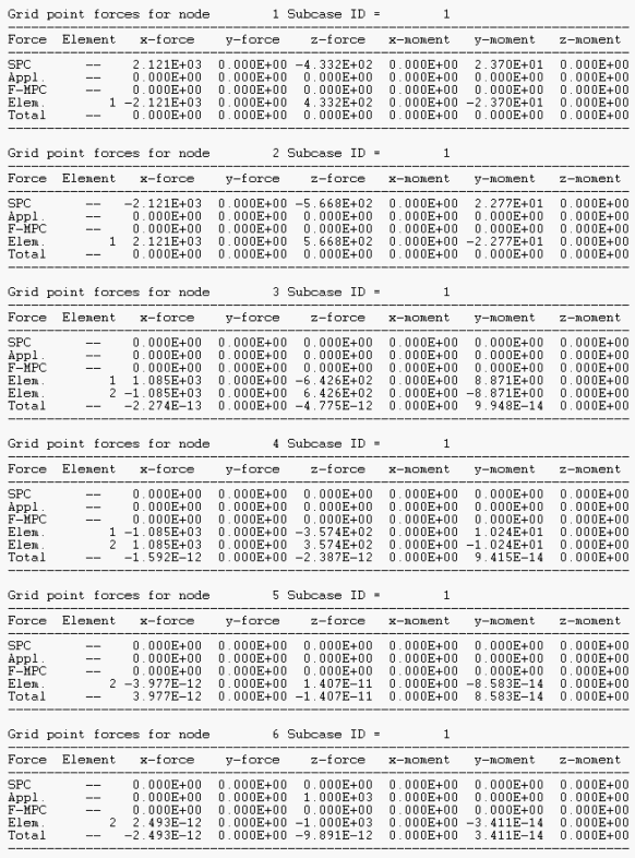

Figure 2.
From the menu bar, click Post > Free Body.

The FBD Forces and Resultant Force and Moment utilities use element and node set definitions to define what information to extract and sum from the GPFORCE table. This information is then used to produce free bodies and/or resultant force and moments.

FBD Forces

The FBD Forces utility uses an element set to define the values to extract from the GPFORCE table.

The FBD Forces utility uses an element set to define which values to extract from the GPFORCE table. This serves several purposes:
  • Any nodes in the element set that have Applied loads will have those values extracted.
  • Any nodes in the element set that have SPC loads will have those values extracted.
  • Any nodes in the element set that have MPC loads will have those values extracted.
  • Any nodes in the element set attached to one or more elements not in the element set will have the appropriate element forces extracted.
The following example of FBD-Forces extraction uses element 1 from the same 2-element image shown at the beginning of this topic.
Element Set
The element set contains only element 1. Element 1 has nodes 1, 2, 3 and 4.
X-Force
Node 1 is only attached to element 1 and has an SPC constraint. Since element 1 is in the element set, its force contributions are not considered. From the GPFORCE table, the x-force value that is extracted for node 1 is the SPC force 2.121e+03.
Node 2 is only attached to element 1 and has an SPC constraint. Since element 1 is in the element set, its force contributions are not considered. From the GPFORCE table, the x-force value that is extracted for node 2 is the SPC force -2.121e+03.
Node 3 is attached to elements 1 and 2. Since element 1 is in the element set, its force contributions are not considered. Since element 2 is not in the element set, its force contributions will be considered. From the GPFORCE table, the x-force value that is extracted for node 3 is the element 2 force -1.085e+03.
Node 4 is attached to elements 1 and 2. Since element 1 is in the element set, its force contributions are not considered. Since element 2 is not in the element set, its force contributions will be considered. From the GPFORCE table, the x-force value that is extracted for node 4 is the element 2 force 1.085e+03.
These values sum to 0.
Y-Force
All values are zero in this model.
Z-Force
Node 1 is only attached to element 1 and has an SPC constraint. Since element 1 is in the element set, its force contributions are not considered. From the GPFORCE table, the x-force value that is extracted for node 1 is the SPC force -4.332e+02.
Node 2 is only attached to element 1 and has an SPC constraint. Since element 1 is in the element set, its force contributions are not considered. From the GPFORCE table, the x-force value that is extracted for node 2 is the SPC force -5.668e+02.
Node 3 is attached to elements 1 and 2. Since element 1 is in the element set, its force contributions are not considered. Since element 2 is not in the element set, its force contributions will be considered. From the GPFORCE table, the x-force value that is extracted for node 3 is the element 2 force 6.426e+02.
Node 4 is attached to elements 1 and 2. Since element 1 is in the element set, its force contributions are not considered. Since element 2 is not in the element set, its force contributions will be considered. From the GPFORCE table, the x-force value that is extracted for node 4 is the element 2 force 3.574e+02.
These values sum to 0.
X-Moment
All values are zero in this model.
Y-Moment
Node 1 is only attached to element 1 and has an SPC constraint. Since element 1 is in the element set, its moment contributions are not considered. From the GPFORCE table, the y-moment value that is extracted for node 1 is the SPC moment 2.370e+01.
Node 2 is only attached to element 1 and has an SPC constraint. Since element 1 is in the element set, its moment contributions are not considered. From the GPFORCE table, the y-moment value that is extracted for node 2 is the SPC moment 2.277e+01.
Node 3 is attached to elements 1 and 2. Since element 1 is in the element set, its moment contributions are not considered. Since element 2 is not in the element set, its moment contributions will be considered. From the GPFORCE table, the y-moment value that is extracted for node 3 is the element 2 moment -8.871e+00.
Node 4 is attached to elements 1 and 2. Since element 1 is in the element set, its moment contributions are not considered. Since element 2 is not in the element set, its moment contributions will be considered. From the GPFORCE table, the y-moment value that is extracted for node 4 is the element 2 moment -1.024e+01.
Additionally, the cross-product of all the forces about the Y axis need to be considered. Selecting node 1 as the summation node (any node in the model can be selected) and performing rXF (all element edge lengths are 0.166) the following is obtained:
Node 1
No additional rXF contributions since it is the sum point
Node 2
-0.166*Fx + 0*Fz = -0.166*-2.121e+03 + 0*-2.121e+03 = 3.535e+02
Node 3
0*Fx + -0.166*Fz = 0*-1.085e+03 + -0.166*6.426e+02 = -1.071e+02
Node 4
-0.166*Fx + -0.166*Fz = -0.166*1.085e+03 + -0.166*3.547e+02 = -2.400e+02
These values sum to about 0.
Since there are only 4 significant digits in the GPFORCE table, the precision of the calculated moments are compromised. In the actual FBD utilities, the full result and machine precisions are used.
Z-Moment
All values are zero in this model.


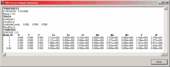
Figure 3. Output Table from the FBD Forces Utility. Element 1 (element set) with node 1 used as the summation point.

Resultant Force and Moment

The Resultant Force and Moment utility uses an element set and a node set (cross-section definition) define the values to extract from the GPFORCE table.

The cross-section definition serves several purposes.
  • All nodes in the node set must be attached to one or more elements in the element set.
  • All nodes in the node set that have Applied loads will be extracted and utilized in Resultant Force and Moment calculations.
  • All nodes in the node set that have SPC loads will be extracted and utilized in Resultant Force and Moment calculations.
  • All nodes in the node set that have MPC loads will be extracted and utilized in Resultant Force and Moment calculations.
  • For all nodes in the node set, Element contributions from only those elements which are not a part of the element set of the cross-section definition will be extracted and utilized in the Resultant Force and Moment calculations.
The following example of Resultant Force and Moment extraction uses element 1 and nodes 3 & 4 from the same example as the previous FBD Forces.
Node Set
The node set contains nodes 3 and 4; the element set contains only element 1.
X-Force
Node 3 is attached to elements 1 and 2. Since element 1 is in the element set, its force contributions are not considered. Since element 2 is not in the element set, its force contributions will be considered. From the GPFORCE table, the x-force value that is extracted for node 3 is the element 2 force -1.085e+03.
Node 4 is attached to elements 1 and 2. Since element 1 is in the element set, its force contributions are not considered. Since element 2 is not in the element set, its force contributions will be considered. From the GPFORCE table, the x-force value that is extracted for node 4 is the element 2 force 1.085e+03.
These values sum to 0.
Y-Force
All values are zero in this model.
Z-Force
Node 3 is attached to elements 1 and 2. Since element 1 is in the element set, its force contributions are not considered. Since element 2 is not in the element set, its force contributions will be considered. From the GPFORCE table, the x-force value that is extracted for node 3 is the element 2 force 6.426e+02.
Node 4 is attached to elements 1 and 2. Since element 1 is in the element set, its force contributions are not considered. Since element 2 is not in the element set, its force contributions will be considered. From the GPFORCE table, the x-force value that is extracted for node 4 is the element 2 force 3.574e+02.
These values sum to 1.000e+03.
X-Moment
All values are zero in this model.
Y-Moment
Node 3 is attached to elements 1 and 2. Since element 1 is in the element set, its moment contributions are not considered. Since element 2 is not in the element set, its moment contributions will be considered. From the GPFORCE table, the y-moment value that is extracted for node 3 is the element 2 moment -8.871e+00.
Node 4 is attached to elements 1 and 2. Since element 1 is in the element set, its moment contributions are not considered. Since element 2 is not in the element set, its moment contributions will be considered. From the GPFORCE table, the y-moment value that is extracted for node 4 is the element 2 moment -1.024e+01.
Additionally, the cross-product of all the forces about the Y axis need to be considered. Selecting node 3 as the summation node (any node in the model can be selected) and performing rXF (all element edge lengths are 0.166) the following is obtained:
Node 3
No additional rXF contributions since it is the sum point
Node 4
-0.166*Fx + 0*Fz = -0.166*1.085e+03 + 0*3.547e+02 = -1.808e+02
These values sum to -2.000e+02. Since there are only four significant digits in the GPFORCE table, the precision of the calculated moments are compromised. In the actual FBD utilities, the full result and machine precisions are used.
Z-Moment
All values are zero in this model.


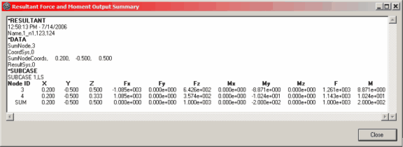
Figure 4. Output Table from the Resultant Force and Moment Utility. For element 1 (element set) and nodes 3 and 4 (node set) with node 3 used as the summation point.

FBD Displacements

The FBD Displacements utility uses an element set and a node set to define the values to extract from the Displacement table.

The element and node sets serve several purposes:
  • All nodes in the node set will have displacement and rotation values extracted.
  • The element set is for visualization and breakout modeling purposes only.

Additional Information

  • Recommended practice is to output GPFORCE data for the element set(s) of interest only. This procedure reduces the size of the .op2 file and helps speed up the FBD Forces extractions. Additionally, for Nastran and OptiStruct, consider using STRESS = NONE and/or DISPLACEMENT = NONE options to further reduce the size of the .op2 file. See the OptiStruct online Reference Guide for more information regarding STRESS and DISPLACEMENT I/O Option cards.
  • MPC forces and moments are properly extracted for the following MPC constraint types:
    RBE2
    RJOINT
    RBE3
    RROD
    Rigidlink
    RBAR
  • The GPFORCE and Displacement results are extracted from the .op2 file in float point precision in binary format. This maintains the integrity of the calculations as well as enhances the performance of the utilities.