This tutorial demonstrates how to find deformation, stress and energy absorbing
capacity of various structural components of a vehicle hitting a stationary or moving
object.
The component is crashworthy (safe) if it meets the plastic strain and energy
targets.
A Bumper beam is one of the components that is used to protect passengers from
front and rear collision.
Bumper beam crash tests are necessary, for instance, to calculate the energy
absorption of this component during a crash.
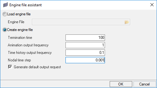
UNITS: Length (mm), Time (ms), Mass (kg)
Simulation time: [0 – 100.0]
Boundary Conditions: Gravity load, initial velocity of -5.0 m/s of the bumper
beam on the rigid wall
/MAT/LAW2 (PLAS_JOHNS): for Bumper parts and Crash box
parts
/PROP/TYPE1 (SHELL): for Bumper beam parts and Crash box
parts
/INTER/TYPE2: for tied interface that connects a set of
secondary nodes to a main surface. (connect coarse and fine meshes, model
spotwelds, rivets, and so on)
/INTER/TYPE7: Penalty contact between all versus all
/FAIL/BIQUAD: to model failure
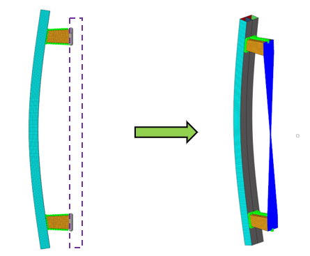
The model used consists of a simplified bumper model: Figure 1. Bumper Model
From the Preferences menu, select User Profiles or click
the
icon in toolbar.
Select Radioss (Radioss2021)
and click OK.
Import the Model
Click File > Import > Solver Deck or click .
Click the Select File icon to open the Bumper_start_0000.rad file you saved to your working directory.
Click Open.
Click Import.
Ignore the warning “No valid Engine File
found…”
Click Close to close the window.
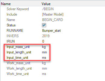
In the Model Browser, verify that the correct units are
defined by expanding Cards, BEGIN_CARD.
Figure 2.
Define Penetration/Intersection Check
From the Tools menu, select Penetration Check.
Change Entity type to Components.
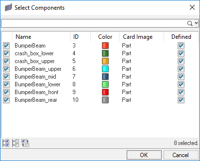
For Selection, click Components, then select the
following components and click Close.
Figure 3.
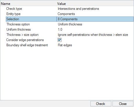
For Thicknesss option, select Uniform Thickness and set
the Value to 1.0.
Select Consider edge penetration.
Figure 4.
Click Check and Close.
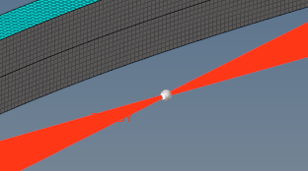
In the Penetrations Browser, click the Review Failed
Elements icon .
Intersections and penetrations will be highlighted.
Click Penetrations, as shown below:
Figure 5.
Click the Automatic Intersection/Penetration Fix icon
to fix penetrations.
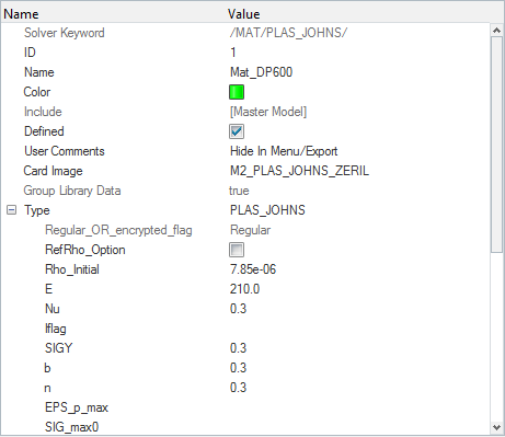
Create Materials
Two materials will be created.
In the Model Browser, right-click and select Create > Material.
In the Entity Editor, for Name, enter
Mat_DP600.
Set Card Image to M2_PLAS_JOHNS_ZERIL.
Insert values, as shown below.
Figure 6.
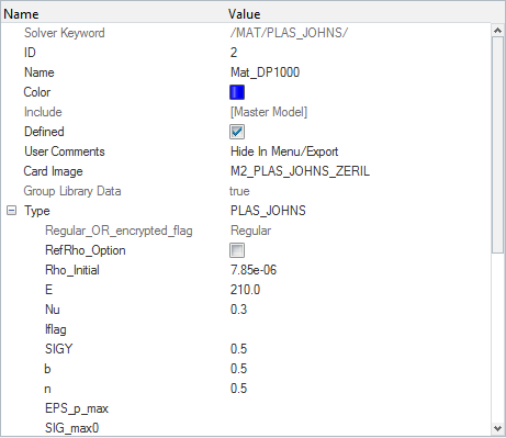
In the Model Browser, right-click and select
Duplicate to duplicate the material.
In the Entity Editor, for Name, enter
Mat_DP1000.
Change values of SIGY, b and n to 0.5.
Figure 7.
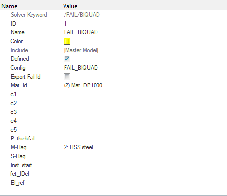
Create Failure to Material Card
In the Model Browser, right-click and select Create > Failure.
In the Entity Editor, for Name, enter
FAIL_BIQUAD.
Set Config to FAIL_BIQUAD.
Set Mat_id, click Material, select
Mat_DP1000 and click OK.
For M-Flag, select 2: HSS steel.
Figure 8.
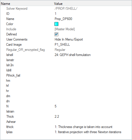
Create the Properties
Two properties will be created.
In the Model Browser, right-click and select Create > Property.
In the Entity Editor, for Name, enter
Prop_DP600.
Set Card image to P1_SHELL.
Insert values for the Crash_Box shell definition.
Figure 9.
In the Model Browser, right-click on the previously created
property, Prop_DP600 and select
Duplicate.
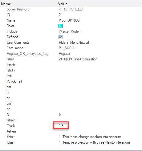
In the Entity Editor, for Name, enter
Prop_DP1000.
Set Card Image to P1_SHELL.
Change the Thick value to 1.8mm.
Figure 10.
Assign Materials and Properties to Components
In the Model Browser, expand the
Components folder and left-click on the
crash_box* components.
In the Entity Editor, for Prop_Id, click the Value
field <unspecified> to change to
Property and select Prop_DP600
and click OK.
For Mat_Id, click the Value field <unspecified> to
change to Material and select
Mat_DP600 and click OK.
In the Model Browser, left-click on the
BumperBeam* components.
In the Entity Editor, for Prop_Id, click the Value
field <unspecified> to change to
Property and select
Prop_DP1000 and click
OK.
For Mat_Id, click the Value field <unspecified> to
change to Material and select
Mat_DP1000 and click OK.
Create Spotwelds
The model has unrealized connectors which will be used to create spotwelds.
From 1D page select connectors > spot and toggle the realize option to connect
the bumper parts.
Click connectors and select
all.
Set type= to type2(spring).
For tolerance and diameter, insert a value of 8 and
click realize.
Click return.
Reflect the Model
From the Tool page, select reflect.
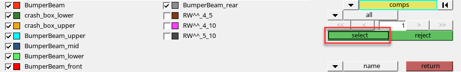
Change the entity selector to elems, then select
elems, by collector and select
the only the Bumper and Crash collectors, as shown. Click
select.
Figure 11.
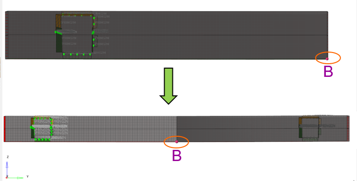
Select elems > duplicate >
original comp.
This will duplicate the element.
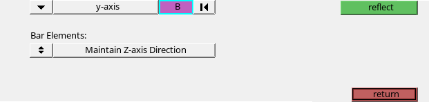
Mirror/reflect the model at Y-axis. Select B as the
basis point.
Figure 12. Figure 13.
Click reflect and return.
From the Tool page, select reflect.
Change the entity selector to connectors, click the
connector entity selector and select
all. Click again and select duplicate > original connector group.
Reflect/mirror the model at Y-axis. Select B as the
basis point.
Click reflect and return to
confirm.
From the 1D page, select connectors and
spot.
Toggle the realize button and click
connectors and select entities using the Shift+left-mouse in the window and draw a box.
Click reflect and return.
Note: Nodes at the midplane are not yet equivalenced.
From the Tool page, select edges.
Select all elements by a box, whose nodes are at free edges. Change the entity
selector to elems amd select
all.
Set tolerance to 0.1mm.
Click preview equiv, equivalence
and return.
Create the Interface for Penalty Contact
Another useful way to view the model is using the Solver Browser
which shows the model using the Solver entities.
From the menu, click View > Solver Browser.
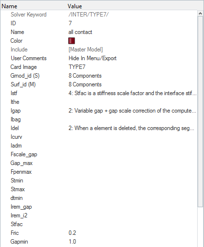
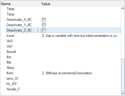
In the Solver Browser, right-click Create > INTER > TYPE7.
In the Entity Editor, for Name, enter
all_contact.
For Grnod_id(s) and Surf_id(M), change the entity selector to
Components and select all parts containing shells
(not the RW^^ components) and click OK.
Insert values, as shown below.
Figure 14.
In the Solver Browser, right-click on the previously
created /INTER/TYPE7 contact
(all_contact) and click
Review.
Right-click on the previously created /INTER/TYPE7 contact
(all_contact) and click Review
to turn off the review.
Create the Rigid Body
Click to
change the view to XY-View.
In the Model Browser, right-click Create > Component to create a new component.
In the Entity Editor, for Name, enter
RBODY.
In the Entity Editor, select the
Rbody option.
Removes the Card Image, Prop_Id, and Mat_Id from the menu since they are
not needed for rigid bodies.
From the main menu, select Mesh > Create > 1D Elements > Rigids.
For nodes 2-n, click the first down arrow and select Multiple
nodes.
For primary node, click the down arrow and select calculate
node.
Click the nodes entity selector. Use a window selection
to select the last row of nodes of the Crash_Boxes by
box. Click proceed and
create.
Figure 15.
From the Solver Browser, select Rbody > MULTIPLE_NODES_RBODY > Elements.
For MASS, enter 500 for the inertia.
For J_XX, J_YY, and J_ZZ, enter 50.
Create the Boundary Condition
Select View > Solver Browser, and right-click in the Solver tab
area.
Select Create > BOUNDARY CONDITIONS > BCS.
For Title, enter Boundary_condition, right-click
grnd_ID and click
Create.
Within the grnd_ID section, click on 0
Nodes beside Entity IDs, then
Nodes.
A nodes selection appears.
Select the nodes, as shown below and
click proceed.
Figure 16.
Activate all degrees of freedom; except of DOF1, translation in the
X-direction.
Create the Gravity Load
Select View > Solver Browser, and right-click in the Solver tab
area.
Select Create > BOUNDARY CONDITIONS > GRAV.
For Title, enter Gravity_load.
Right-click on grnd_ID and select
Create.
Within the grnd_ID section, for Name, enter
all_nodes.
Click on 0 Nodes beside Entity IDs, then
Nodes.
A node selection appears.
Click on the nodes entity selector and select “all” to
select all the nodes.
Click proceed.
For Dir, select Z as the gravity direction.
Set Fscale(Y) to -1 to apply
gravity in the negative direction.
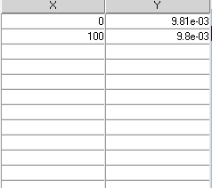
Right-click on fct_ID(T) and select
Create.
Right-click on fct_ID(T) and select Plot
Curve.
An XY curve editor appears.
Enter the values, as shown below.
Figure 17.
Create the Initial Velocity
Select View > Solver Browser, and right-click in the Solver tab
area.
Select Create > BOUNDARY CONDITIONS > INIVEL.
For Title, enter INIVEL.
Click Set beside grnd_ID and pick the
all_nodes set that was created in the gravity
creation set.
Click Velocity Components and enter, -5, 0,
0 for Vx, Vy and Vz fields, respectively.
Define the Rigid Wall
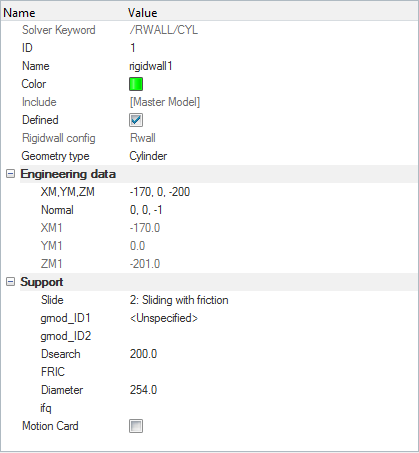
Right-click in the Solver Browser and select Create > RWALL > CYL.
For Name, enter RWALL.
For XM, YM, ZM, enter -170, 0, -200, respectively.
For Normal, enter 0, 0, -1, respectively.
For Sliding, select 2: Sliding with friction.
For FRIC, enter 0.2.
For Dsearch, enter 200.0mm.
For Diameter, enter 254.0mm.
Figure 18.
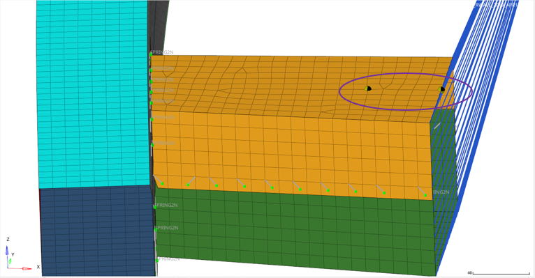
Create Accelerometer for Post-Processing
Right-click in the Solver Browser and select Create > ACCEL.
For name, enterACCELER01.
For Fcut, enter 1.650.
For node_ID, click Node and select the node to the left
in Figure 19 .
Figure 19.
In the Solver Browser, right-click on the previously
created accelerometer, ACCELER01 and click
Duplicate.
A new Accelerometer is created.
Click on the new accelerometer and rename to
ACCELER02.
For node_ID, click Node and select the node to the right
in Figure 19.
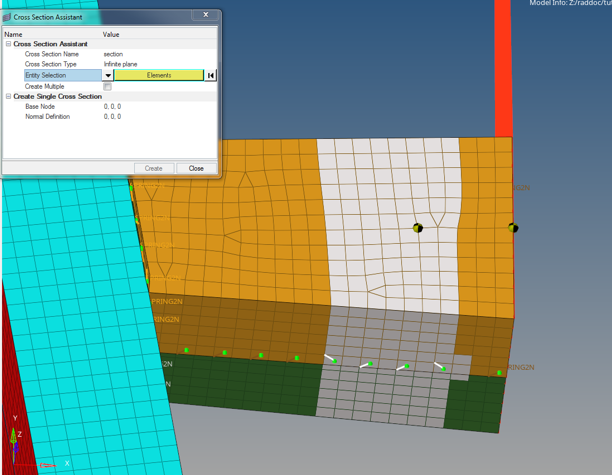
Create a Cross Section
Right-click in the Model Browser and select Create > Cross Section.
A Cross Section Assistant opens.
For Cross Section Name, enter section.
For Entity Selection, click Components and change to
Elements.
Figure 20.
Select elements in left crushbox using a window and click
proceed.
For Base Node, select the arrow to pick a node that defines the base
node.
Select the node on bumper side of the accelerometers and click
proceed.
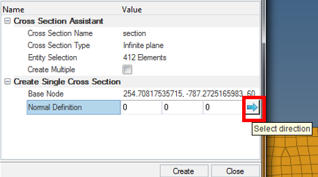
For Normal Direction, click the Select direction arrow
to pick a node.
Figure 21.
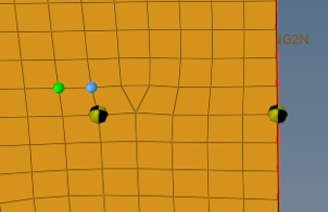
Click N1 to set N1 and N2, as shown, which defines the
normal vector and click proceed.
Figure 22.
Click Create, then click
Close.
Review the Cross Section
In the Model Browser left-click on the cross section
section and right-click and select
review, or press the Q on the
keyboard.
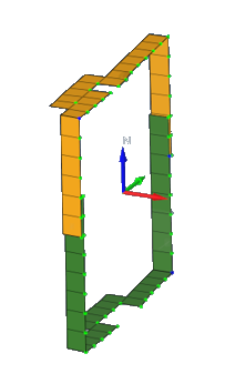
If the nodes and element were not exactly on the plane, the automatic
selection needs to be modified. See Edit the Cross Section Sets. Figure 23.
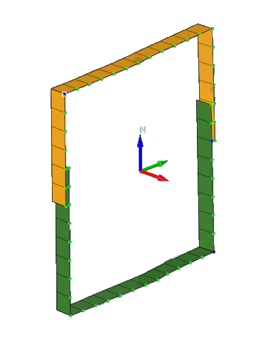
If the nodes and elements are exactly are in one row, press
Q to turn off the review.
Figure 24.
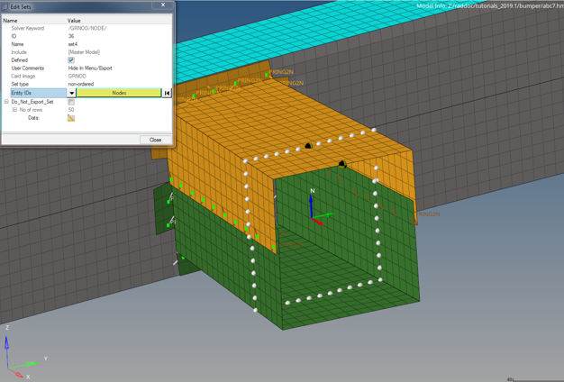
Edit the Cross Section Sets
With the section still selected, open the Entity Editor
and right-click on grshel_id and select
edit to edit the set of elements that defines the
section.
Click beside Entity IDs twice to edite the elements in the set.
Left-click to select and right-click to deselect elements until all the
elements selected are in a row.
Click proceed and then click
Close.
In the Entity Editor, right-click
grnod_id and select edit to
edit the set of nodes that defines the section.
Click beside Entity IDs twice to edit the nodes in the set.
Left-click to select and right-click to deselect nodes until all the nodes
selected are in a row, as shown.

 icon in toolbar.
 .
.
 to open the Bumper_start_0000.rad file you saved to your working directory.
 .
Intersections and penetrations will be highlighted.
.
Intersections and penetrations will be highlighted.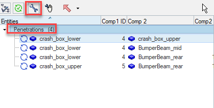
 to fix penetrations.
 to
change the view to XY-View.
to
change the view to XY-View.
 .
.
 , if there are any penetrations or intersections.
 .
.
 and navigate to the
destination directory where you want to export to.
and navigate to the
destination directory where you want to export to.