The generic ASCII reader provides a lot of flexibility
in defining results that are imported to HyperView, however
certain restrictions apply to how the data is formatted.
The following guidelines are suggested when creating ASCII files:
General Rules
The extension of the file containing the ASCII
data is recommended to be *.hwascii. Other file extensions
are allowed, however the filter in the File Open dialog is
set to look for *.hwascii files.
The first line in the ASCII file must contain
"ALTAIR ASCII FILE" in header (which identifies the file type).
The columns should be separated by delimiters such as: <SPACE> <TAB>, ; :
. (except for # and $). A single delimiter should be used per file.
Any line that starts with a # - is treated as a comment line.
A line that starts with $ - is considered to be the data header. Data header
lines can be defined in any order.
A line that does not start with $ - is considered to be the data block.
The keywords in the data header are case insensitive.
If keywords are not in the header; defaults will be assumed.
If duplicate records exist in a given loadstep for any entity (nodes/elements,
and so on), only the last valid value will be considered.
Blank lines will be ignored.
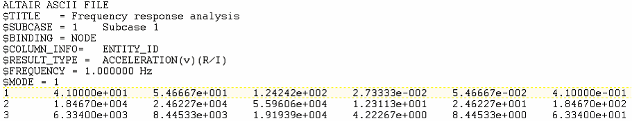
A sample header with various keywords is shown below: Figure 1.
Additional Rules and Guidelines
Number of data values for each of the result types (mandatory):
RES(v) 3 (6 for complex results)
RES(t) 6 (12 for complex results)
RES(2t) 3 (6 for complex results)
RES(s) 1 (2 for complex results)
The order of data for each of the result types:
Vector – X,Y,Z.
Tensor – XX,YY,ZZ,XY,YZ,ZX.
Complex – Real (Mag) values for all the components followed by
Imaginary (Phase) values.
If the layer results are given - the data has to be repeated for
each layer.
The Result Data needs to be specified as per the sequence specified at the
$RESULT_TYPE header.
If GRID_ID is specified in the header, the Result Data is repeated at each
node (or corner nodes) of the Element. When specifying the corner data, the
grid ID or the corner index must match the order of the connectivity of the
element. Mixing the order can result in undesirable data being associated to
the corners.
If the header block does not contain any information about the Subcase,
Simulation, and Data Type, then the same information is taken from last
header read.
If the header contains the keyword $INCLUDE, then data are given in external
file with the given path.
Note: The include file should contain only
data.
If the units for $FREQUENCY (or $TIME) is to be provided, then it has to be
given after the sync value (separated with a space).
If $SUBCASE and $FREQUENCY (or $TIME) is not specified, then it is a static
analysis in one subcase.
If there is no $BINDING, then the default binding is Element.
If there is no $LAYER_INFO, then only one layer (mid) is assumed.
If a data type has multiple layers associated with it, the layers will be
listed layer-by-layer for each entity (meaning that for a given entity, all
of the data, including corner data, has to be specified
layer-by-layer).
The layer label should be given in quotes if the label has blank space in it
(for example, "Ply 1").
The coordinate system ID is specified if the results are output in a
particular local coordinate system. These are typically user defined systems
in the model. If there is no SYS_ID, then the results are in the global
coordinate system:
SYS_ID = 0 - the results are in the global coordinate system.
SYS_ID = -1 - the results are in the elemental system.
If there is no ID_POOL, then default pools like “Nodes” and “Elements” are
created.
If there is no GRID_ID, then only centroidal results are given. GRID_ID = 0
- implies a centroidal result.
If there is no (R/I) or (M/P) - then the results are real (non complex).
With complex results, the phase angle is specified in degrees.
If there is "Anim Source" after a nodal vector result type, then this data
type will be used as an animation source. If not, the first vector type will
be used as animation source by default.
More than one source of animation is allowed.
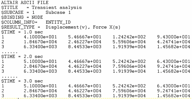
A sample portion of a file with transient results is shown below: Figure 2.