RD-T: 3060 Three Point Bending
This tutorial demonstrates how to set up 3-point bending model with symmetric boundary conditions in Y direction.
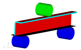
図 1.
The model description is as follows:
- UNITS: Length (mm), Time (s), Mass (ton), Force (N) and Stress (MPa)
- Simulation time: in Engine file [0 - 6.601e-002 s]
- Only one half of the model is modeled because it is symmetric.
- The supports are totally fixed. An imposed velocity of 1000 mm/s is applied on the Impactor in the (-Z) direction
- Model size = 370mm x 46.5mm x 159mm
- Honeycomb Material /MAT/LAW28: HONEYCOMB
[Rho_I] Initial density = 3.0e-10ton/mm3
[E11], [E22] and [E33] Young's modulus (Eij) = 200 MPa
[G11], [G22] and [G33] Shear modulus (Gij) = 150 MPa
- Elasto-Plastic Material /MAT/LAW36: Inner, Outer and
Flat
[Rho_I] Initial density = 7.85-9ton/mm3
[E] Young's modulus = 210000 MPa
[nu] Poisson's ratio = 0.29
- Strain Curve:
0 1 2 3 4 5 6 7 8 9 STRAIN 0 0.012002 0.014003 0.018003 0.022002 0.026003 0.030006 0.032 0.033005 0.033523 STRESS 325 335.968 343783 349.245 358.649 372.309 383.925 388.109 389.292 389.506 - Elastic Material /MAT/PLAS_JOHNS: Impactor
[Rho_I] Initial density = 8e-9ton/mm3
[E] Young's modulus = 208000 MPa
[nu] Poisson's ratio = 0.29
Model Files
必要なモデルファイルのダウンロードについては、モデルファイルへのアクセスを参照してください。
Start HyperCrash
- Open HyperCrash.
- Set the User profile to RadiossV2022 and the Unit system to N_mm_s_T.
- Set User Interface style as New.
- Set your working directory to where the downloaded file is located.
- Click Run.
- Click .
- In the input window, select BENDING_0000.rad.
- Click OK.
Create and Assign Material
-
In the window, right-click and select as shown below:
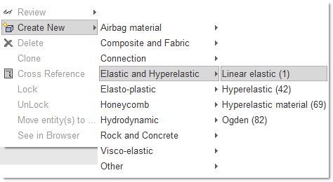
図 2. - Enter all the material data, as shown in the following image.
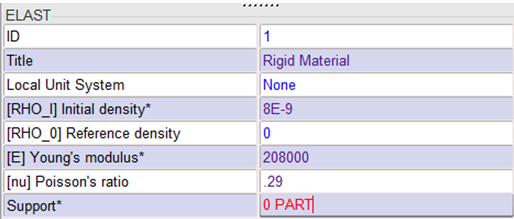
図 3. -
Right-click in the entry box
Support, and click Include picked
parts
 to select the parts
Impactor and Support in the
モデリングウィンドウ.
to select the parts
Impactor and Support in the
モデリングウィンドウ.
Create and Assign Material for Parts
- Enter all the material data, as shown in the following image:
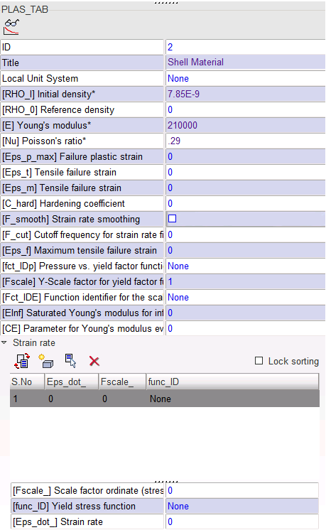
図 4. -
Open the Strain rate folder and click
 to add a row.
-
Right-click in Yield stress function field and click
Select in Model to select an existing function in the
model.
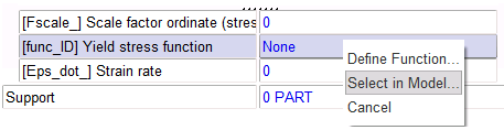
図 5. -
In the Function file window, select the function with an ID of
2, then click OK to import the
curve. The function can be edited, as shown in the image below.
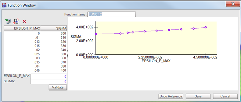
図 6. -
Click
 to isolate
this selection.
to isolate
this selection.
-
Right-click in the entry box
Support, and click Include picked
parts
to select the parts
Inner, Outer and
Flat in the モデリングウィンドウ
as shown in the image.
図 7.
Create and Assign HCFoam Material
-
Enter all the material data, as shown in the image:
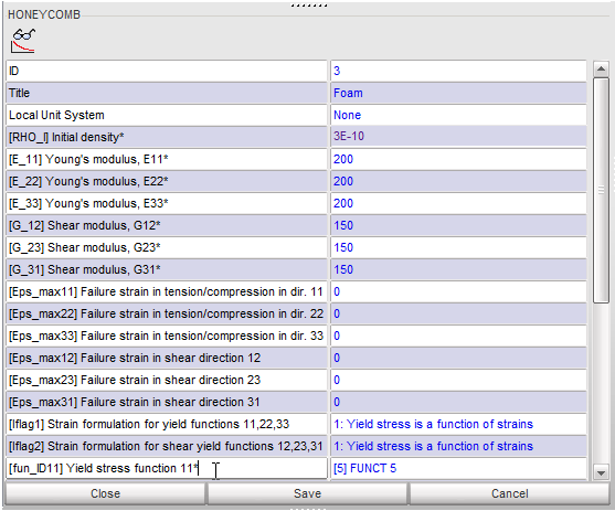
図 8. -
Repeat this process for the Yield functions, as shown in the following
image.
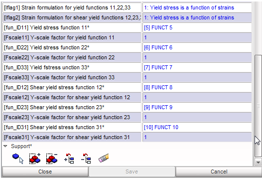
図 9. -
Click to isolate
this selection.
-
Right-click in the entry box
Support, and click Include picked
parts
to select
HCFoam in the モデリングウィンドウ as
shown in the image.
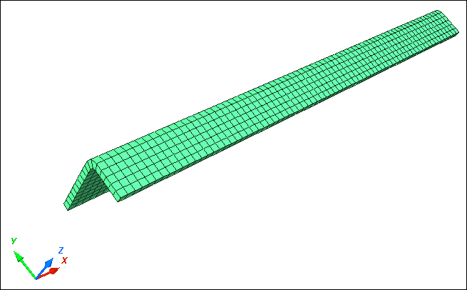
図 10.
Create and Assign a Property
-
In the window, right-click and select .
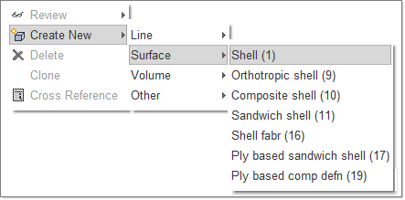
図 11. -
Enter Shell thickness and Shell element formulation values, as shown in the
image.
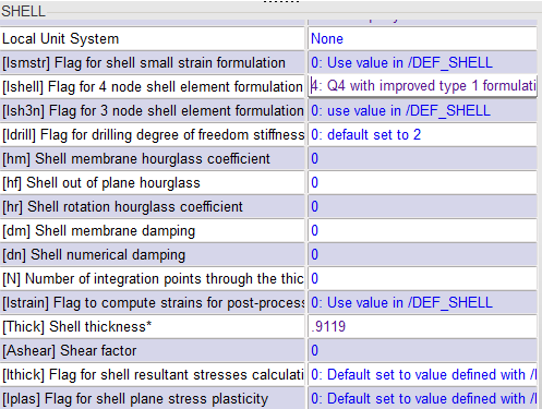
図 12. -
Click to isolate
this selection.
-
Right-click in the entry box
Support, and click Include picked
parts
to select the parts
Inner, Outer and
Flat in the モデリングウィンドウ
to assign Shell property.
Create and Assign an Impactor and Support Property
-
Enter the Shell thickness value as .9119, as shown in
the image.
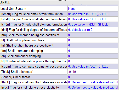
図 13. -
Click
 to show
only these parts.
to show
only these parts.
-
Right-click in the entry box
Support, and click Include picked
parts
to selects Impactor and Support in the
モデリングウィンドウ to assign Rigid property.
Create and Assign HCFoam Property
-
Click to isolate
this selection.
-
In the Flag for solid elements formulation field, select
HEPH.
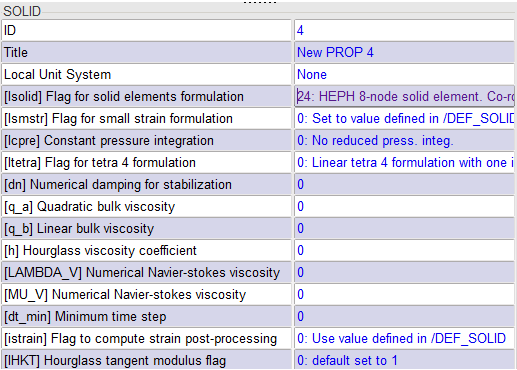
図 14. -
Right-click in the entry box
Support, and click Include picked
parts
to select
HCfoam in the モデリングウィンドウ to
assign Foam property.
Create Impactor Rigid Body
-
Click to show
all parts.
-
Right-click in the entry box
Support, and click Include picked
parts
to select
Impactor in the モデリングウィンドウ.
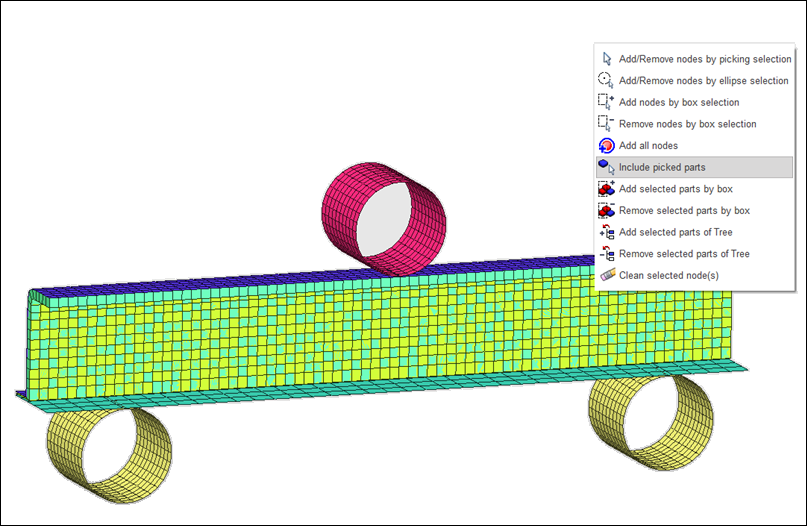
図 15.
Create a Support Rigid Body
-
Right-click in the entry box
Support, and click Include picked
parts
to select
Support in the モデリングウィンドウ.
-
Click Save.
The rigid body for Support should look like the following image.
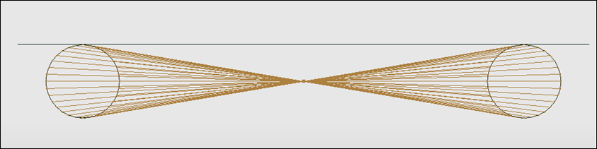
図 16.
Define Boundary Conditions
-
Right-click in the entry box Support and right-click in
the モデリングウィンドウ. Click Add/Remove nodes
by picking selection and select the main node of the rigid
body.
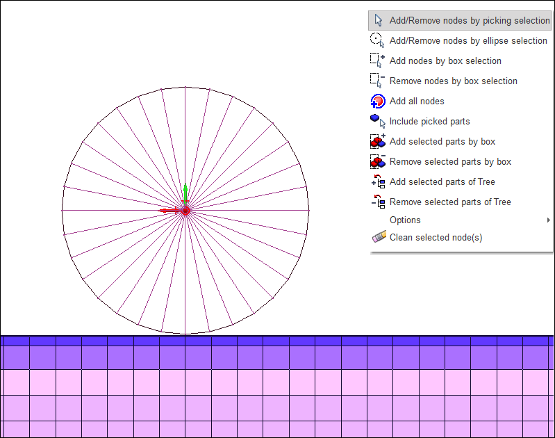
図 17. -
Constrain all DOF except translation in Z as shown in the following image. To
constrain the nodes, check the boxes for TX,
TY, RX,
RY and RZ.
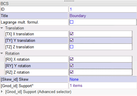
図 18. -
Click the node selection icon
 to select the main node of
Support, as shown in the following image.
to select the main node of
Support, as shown in the following image.
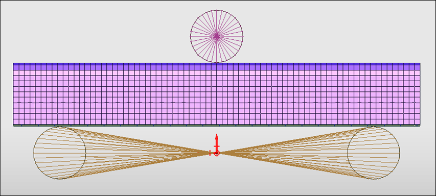
図 19. -
Constrain all DOF by selecting TX,
TY, TZ,
RX, RY and
RZ, as shown in the image.
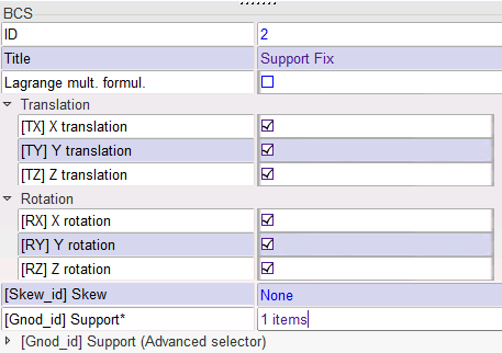
図 20. -
Click to isolate
this selection.
- From the Visualization toolbar, select the YZ View, as shown below.
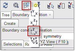
図 21. -
Right-click in the entry box Support, right-click in the
モデリングウィンドウ, and click Add nodes by
box selection to select the nodes, as shown below.
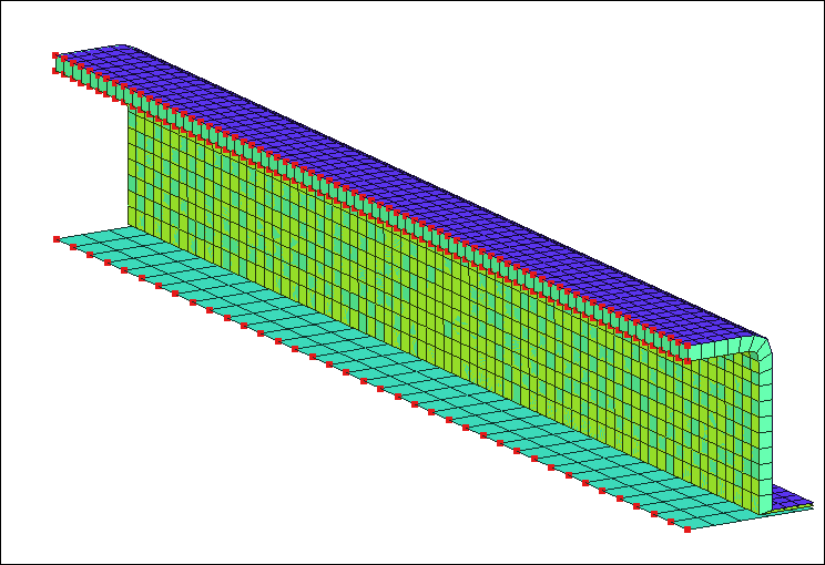
図 22. -
To constrain the nodes, select TY,
RX and RZ.
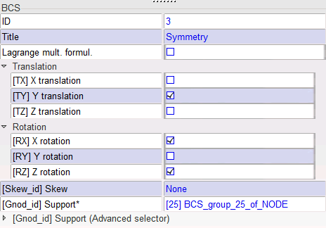
図 23.
Define Imposed Velocity
-
Click in the entry box Support and right-click in the
モデリングウィンドウ. Click
 and select the main node of Impactor.
-
Click Yes in the lower-right corner.
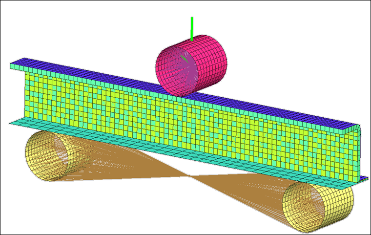
図 24.
Define Contacts
-
Click to isolate
this selection.
-
Press Y or click Yes at the
bottom right of the screen.
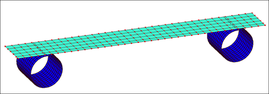
図 25. -
Click to isolate
this selection.
-
Select Outer Part as Secondary and
Impactor as Main, as shown in
the image.
図 26. -
Click to isolate
this selection.
-
Select components Outer, Inner
and Flat, as shown in the image.
図 27.
Clean the Model
-
Click .
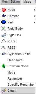
図 28.
Export the Model
-
Click and select the control cards in the images below.
注: Make sure to save each control card before editing the next.
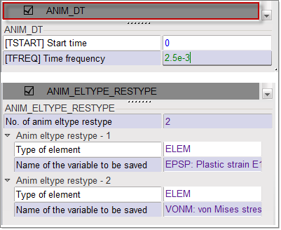
図 29.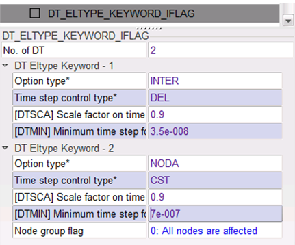
図 30.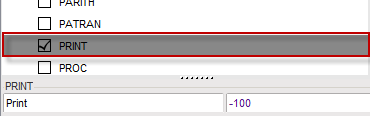
図 31.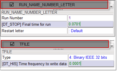
図 32.