RD-T: 3030 Buckling of a Tube Using Half Tube Mesh
This tutorial simulates buckling of a tube using half tube mesh with symmetric boundary conditions.
The figure illustrates the structural model used for this tutorial: a half tube with
a rectangular section (38.1 x 25.4 mm) and length of 203 mm.
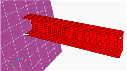
図 1. Model
図 1. Model
The model description is as follows:
- UNITS: Length (mm), Time (ms), Mass (kg), Force (kN) and Stress (GPa)
- Simulation time: Engine [0 - 10 ms]
- The tube thickness is 0.914 mm.
- An imposed velocity of 13.3 mm/ms (~30 MPH) is applied to the right end of the tube
- Elasto plastic material using Johnson-Cook law /MAT/PLAS_JOHNS (STEEL).
[Rho_Initial] Initial density = 7.85e-6 Kg/mm3
[E] Young's modulus = 210 GPa
[nu] Poisson coefficient = 0.3
[a] Yield Stress = 0.206 GPa
[b] Hardening Parameter = 0.450 GPa
[n] Hardening Exponent = 0.5
Model Files
必要なモデルファイルのダウンロードについては、モデルファイルへのアクセスを参照してください。
Input file for this tutorial: BOXTUBE_0000.rad
Start HyperCrash
- Open HyperCrash.
- Set the User profile to RadiossV2022 and the Unit system to kN mm ms.kg.
- Set User Interface style as New.
- Set your working directory to where the downloaded file is located.
- Click Run.
- Click .
- In the input window, select BOXTUBE_0000.rad.
- Click OK.
Create and Assign a Material
-
In the Material tab, right-click and choose .
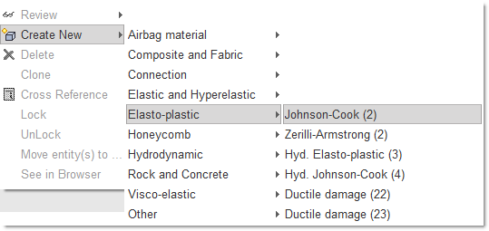
図 2. -
Enter all the material data, as shown.
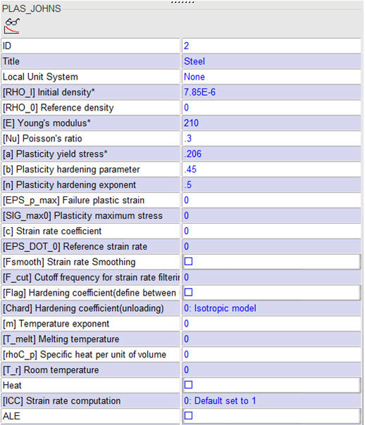
図 3. -
Select Include picked parts
 and select boxtube
in the モデリングウィンドウ.
and select boxtube
in the モデリングウィンドウ.
Create and Assign a Property
-
In the Property tab, right-click and select .
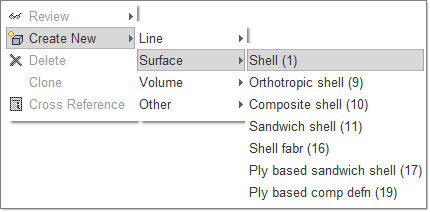
図 4. -
For Shell thickness, enter 0.914.
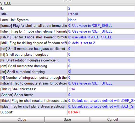
図 5. -
Select Include picked parts
and select boxtube
in the モデリングウィンドウ.
Define the Rigid Body
-
Right-click in the モデリングウィンドウ and select
Add nodes by box selection icon
 to select the nodes in the モデリングウィンドウ, as shown below:
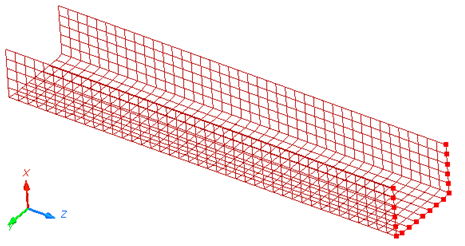
図 6. -
Press Enter or click Save to
validate.
図 7.注: For the remainder of the tutorial, you need to have the ID of the main node of the rigid body. -
Click Show Node Info icon
 in the toolbar, and select the rigid body main node
in the モデリングウィンドウ.
The Node ID appears in the message window (node ID: 803).
in the toolbar, and select the rigid body main node
in the モデリングウィンドウ.
The Node ID appears in the message window (node ID: 803).
Define Boundary Conditions
-
To constrain the nodes, toggle Tx,
Ty, Rx,
Ry and Rz.
図 8.
Define Boundary Conditions Representing Symmetry
-
Select Add nodes by box selection icon to select the nodes in the モデリングウィンドウ, as shown below:
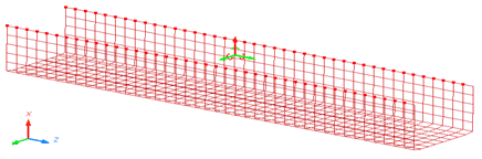
図 9.
Define the Imposed Velocity
-
Click Save and then click
Close.
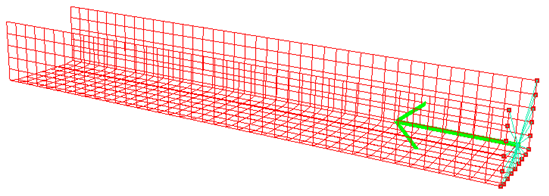
図 10.
Define a Rigid Wall
-
Click See to visualize it in the モデリングウィンドウ.
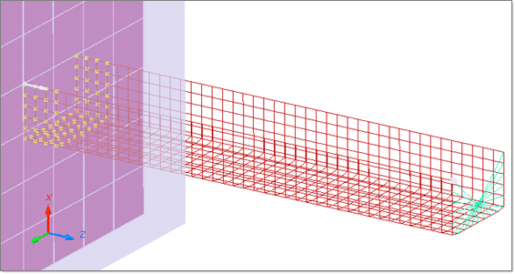
図 11.
Create a Self Contact for the Tube
-
Toggle Self impact.
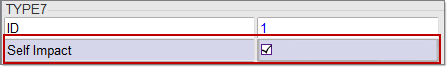
図 12. -
Right-click in the モデリングウィンドウ, and select
Include picked parts icon and select the part in the モデリングウィンドウ.
Export the Model
-
Check Control Card to activate it.
注: Make sure to save it before moving to the next Control Card.
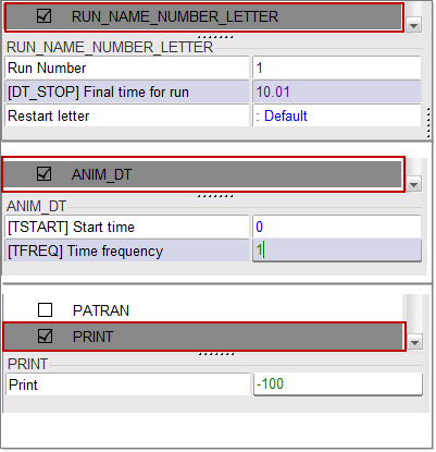
図 13.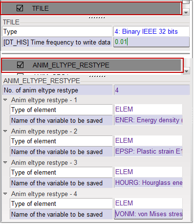
図 14.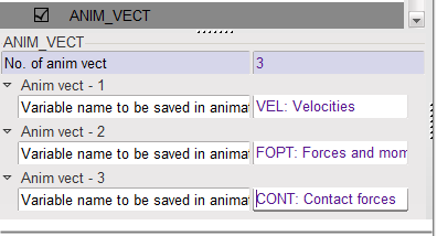
図 15.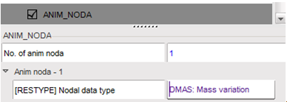
図 16.
Open Compute Console from the Windows Start Menu
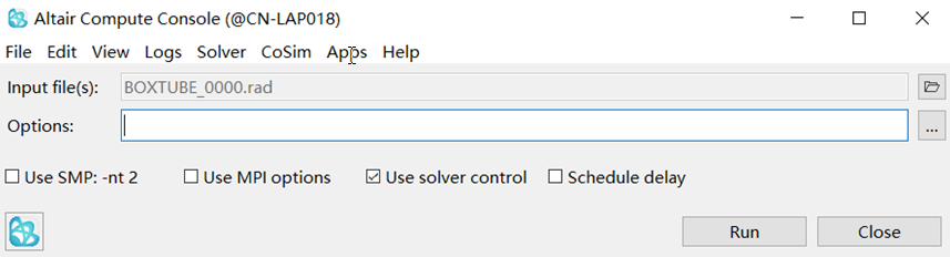
図 17.
Review the Results
Using HyperView, plot the displacement and strain
contour at 10 ms.
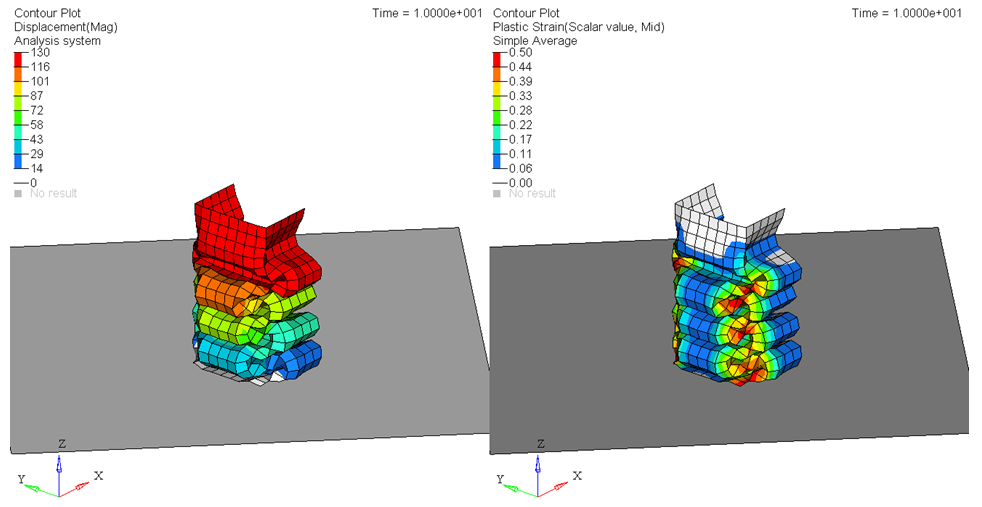
図 18.
図 18.