OS-T: 6050 Dang Van Criterion (Factor of Safety)
The Dang Van criterion is used to predict if a component will fail in its entire load history.
The conventional fatigue result that specifies the minimum fatigue cycles to failure is not applicable in such cases. It is necessary to consider if any fatigue damage will occur during the entire load history of the component. If damage does occur, the component cannot experience infinite life.
The following file found in the optistruct.zip file is needed to perform this tutorial. Refer to Access the Model Files.
Spring-link.fem
or
A copy of the model file used in this tutorial is available on <install_directory>/tutorials/hwsolvers/optistruct.
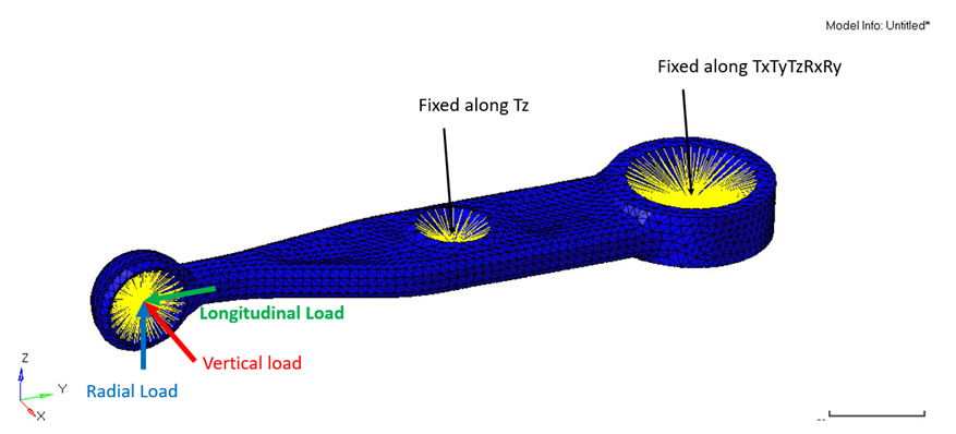
Figure 1. Spring-link for Fatigue Analysis Model
Launch HyperMesh and Set the OptiStruct User Profile
The model being used for this exercise is that of a control arm (Figure 6). Loads and boundary conditions and two static loadcases have already been defined on this model.
Import the Model
-
Select the Files icon
 .
A Select OptiStruct file browser opens.
.
A Select OptiStruct file browser opens. -
Click Import, then click Close to
close the Import tab.
The outline of the Fatigue Analysis setup to be achieved in the following steps.
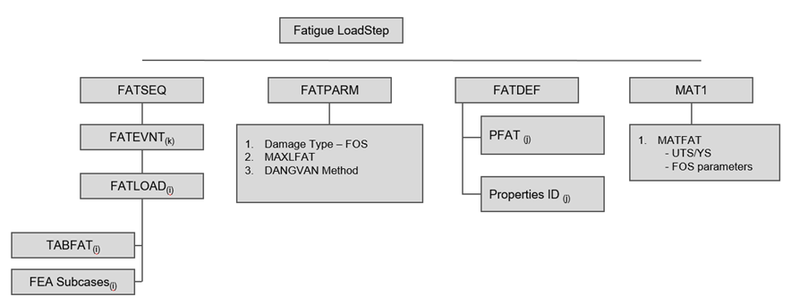
Figure 2. Fatigue Setup - FOS
Set Up the Model
Define TABFAT Load Collector
The first step in defining the loading sequence is to define the TABFAT cards. This card represents the loading history.
- In the Model Browser, right-click and select .
- For Name, enter TABFAT.
- For Card Image, select TABFAT from the drop-down menu.
- For TABLEFAT_NUM, enter 2.
-
Click on the Table icon
 next to the Data: field, enter 1 in row1 and enter
-1 in row2 as the y values.
next to the Data: field, enter 1 in row1 and enter
-1 in row2 as the y values.
- Click Close.
Define FATLOAD Load Collector
Define FATEVNT Load Collector
Create an event to assign the fatloads created.
- In the Model Browser, right-click and select .
- For Name, enter FATEVENT_1.
- For Card Image, select FATEVNT.
- For FATEVNT_NUM_FLOAD, enter 3.
-
Click on the Table icon next to the Data
field and select FATLOAD_Vertical,
FATLOAD_Longitudinal and
FATLOAD_Radial for FLOAD in the pop-out window.
Define FATSEQ Load Collector
Define Fatigue Parameters
Edit Material Data Card
This step instructs on how to add torsional fatigue limit and hydrostatic stress sensitivity.
TFL and HSS are required for calculating the FOS by Dang Van Criterion.
- From Materials, select Mat1_FOS.
- Activate MATFAT.
- For UTS, enter 600 MPa.
- Scroll down and activate FOS.
- For TFL, enter 102.0.
- For HSS, enter 0.424.
- Click Close to exit the material card.
Define PFAT Load Collector
- In the Model Browser, right-click and select .
- For Name, enter pfat.
- For Card Image, select PFAT.
- Set LAYER to TOP.
- Set FINISH to NONE.
- Set TRTMENT to NONE.
- Set Kf to 1.0.
Define FATDEF Load Collector
- In the Model Browser, right-click and select .
- For Name, enter fatdef.
- Set the Card Image to FATDEF.
- Activate PTYPE and PSOLID in the PTYPE Entity Editor.
- Edit FATDEF_PSOLID_NUMIDS to 1.
- Select spring_link for PID and pfat for PFATID.
Define the Fatigue Load Step
- In the Model Browser, right-click and select .
- For Name, enter Fatigue.
- Set the Analysis type to fatigue.
- For FATDEF, select fatdef.
- For FATPARM, select fatparam.
- For FATSEQ, select fatseq.
Submit the Job
Review the Results
-
On the Results toolbar, click
 to open the
Contour panel.
to open the
Contour panel.
-
Set Result type to FOS and click on
Apply to contour the elements.
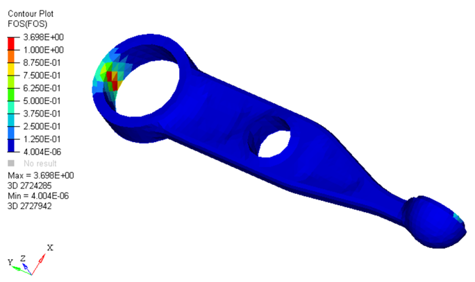
Figure 3. Dang Van Contour Plot