Spot Weld Fatigue (FPM) using S-N Method
Spot weld fatigue can only be applied to spot welds between two shells. The spot weld location is defined by three attributes, sheet 1, sheet 2, and the nugget. The sheets are defined by shell elements, and the nugget is defined by CWELD, CBAR, CBEAM, or CHEXA elements. The nugget can be directly connected to the shells or RBE2/RBE3 elements can be used to connect the nugget to the shells.
The following file found in the optistruct.zip file is needed to perform this tutorial. Refer to Access the Model Files.
SpotWeld_CbarNugget.fem
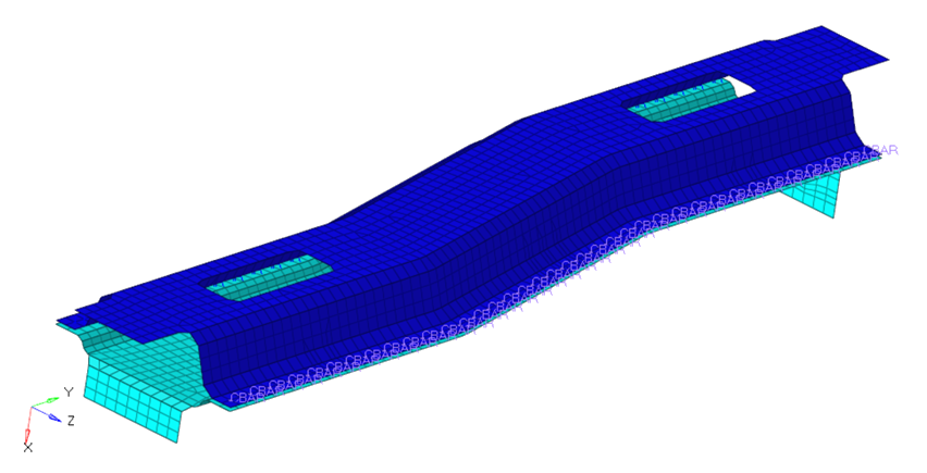
Figure 1. Spot Welds Modeled between Two Frame Sections
- Launch Fatigue Process Manager
- Import a model
- Create fatigue subcase
- Define fatigue analysis parameters
- Define fatigue elements and S-N properties
- Define load-time history and loading sequence
- Submit the job
- View results summary and launch HyperView for post-processing
Launch HyperMesh and Set the OptiStruct User Profile
The model being used for this exercise is that of an automotive frame (Figure 1). The input file consists of 3 static loadsteps to which the frame is subjected to – Frontal torsion, Rear torsion and the Vertical bending.
Import the Model
-
Select the Files icon
 .
A Select OptiStruct file browser opens.
.
A Select OptiStruct file browser opens. -
Click Import, then click Close to
close the Import tab.
The outline of the Fatigue Analysis setup to be achieved in the following steps.
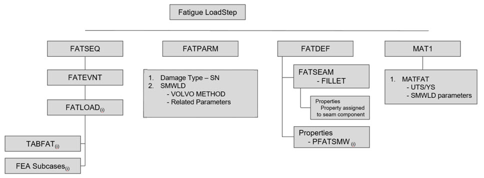
Figure 2. Fatigue Setup – Spot Welds
Set Up the Model
Create a Fatigue Subcase
-
Click Apply.
This saves the current definitions and guides you to the next task Analysis Parameters of the Fatigue Analysis tree.
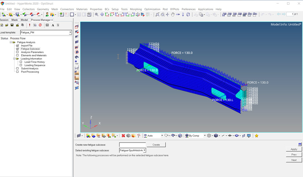
Figure 3. Create and Select Active Fatigue Subcase to Process
Define Fatigue Parameters
Add Fatigue Elements and Materials
Make sure the task Elements and Materials is selected in the Fatigue Analysis tree.
-
Click Add Material.
A Material Data window opens.
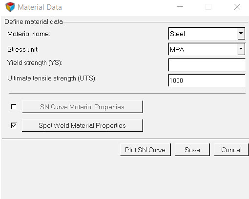
Figure 4. Material Data Definition -
Enter the values for Mean Stress Sensitivity, MSS2, Structural SN Curve along
with bending and membrane SN curve material values, as shown below.
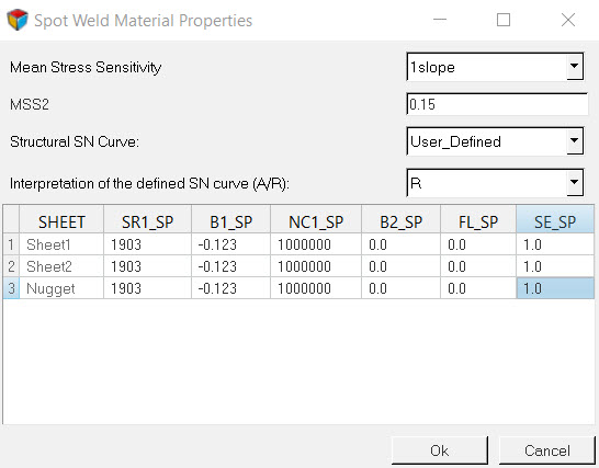
Figure 5. Spot Weld Material Properties dialog -
Click Add Property.
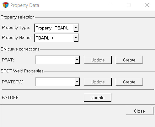
Figure 6. Property Data dialog
Define PFATSPW Property
- In the Model Browser, right-click and select .
- For Name, enter PFATSPW.
- For Card Image, select PFATSPW.
- Set SPTFAIL to All.
- Set ALPHA to 3.5.
- Set TREF to 1.0.
- Set TREF_N to 0.2.
- Set SF to 1.0.
- Click Close.
Define FATDEF Load Collector
-
Select PBARL_4 for PID and
PFATSPW for PFATSPW.
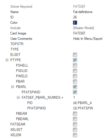
Figure 7. Fatigue Definition showing the combination of Weld Element Properties
Apply Load-Time History
-
Click the Open load-time file icon .
An Open file browser window opens.
-
Click .
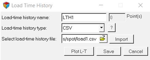
Figure 8. Import Load-Time History -
Click Apply.
This saves the current definitions and guides you to the next task Loading Sequences of the Fatigue Analysis tree.
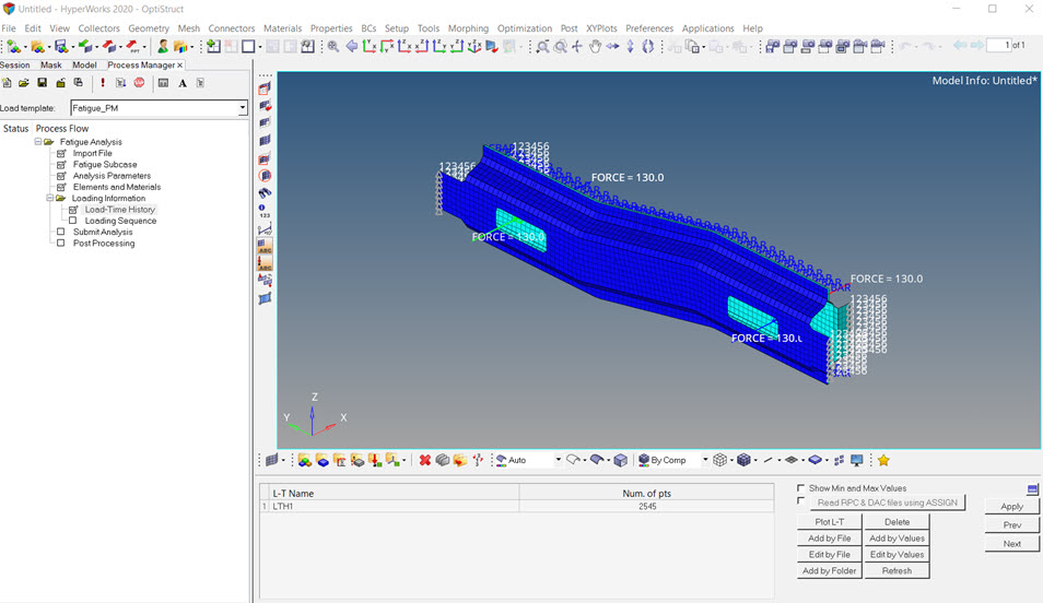
Figure 9. Load-Time History DefinitionNote: The RPC/RSP and DAC file formats are now supported in fpm. Make sure to use HyperMesh Desktop application for this.
Load Sequences
-
Set LDM to 0.1 and Scale to 3.0 for all three
cases.
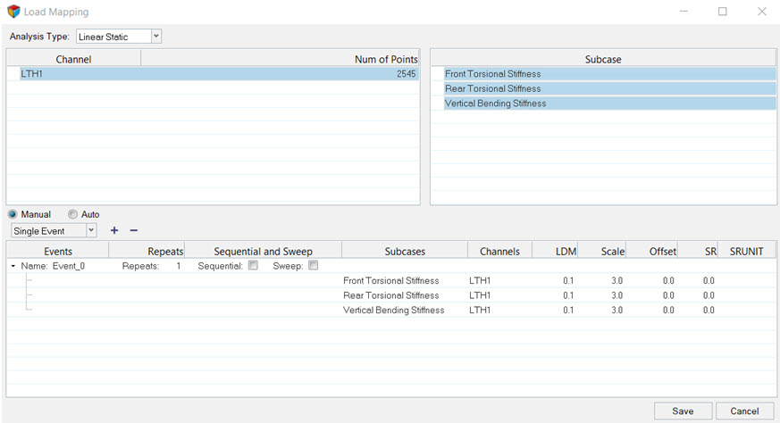
Figure 10. Load Mapping to associate load-time history with static subcase -
Click Save to close the window and create the fatique
event using selected subcases and channels.

Figure 11. Loading Sequences Definition
Submit the Job
Make sure the task Submit Analysis is selected in the Fatigue Analysis tree.
Post-process the Analysis
-
Click Exit to unload Fatigue Process Manager.
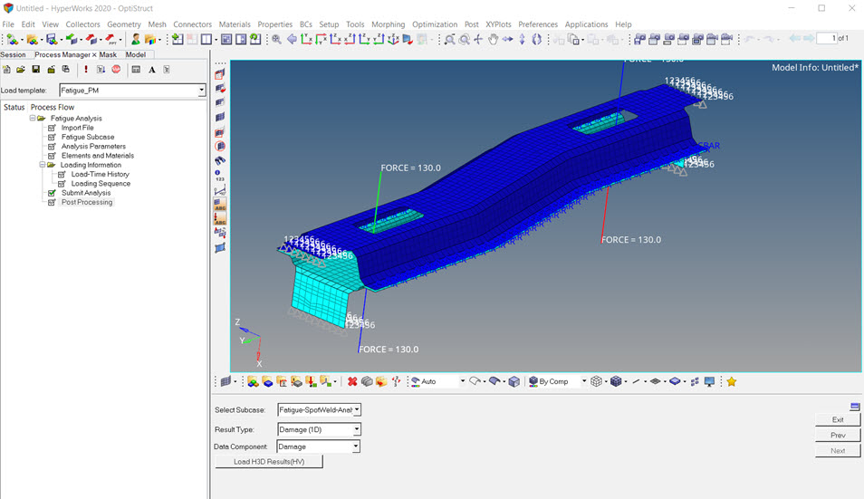
Figure 12. Post-Processing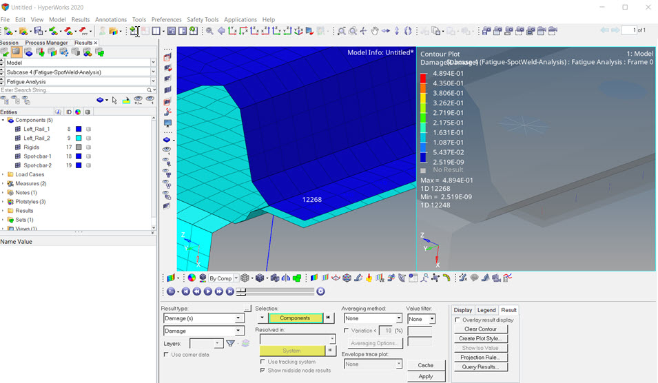
Figure 13. Damage Contour in HyperView