OS-V: 0230 3D Loaded Pin
Contacts Benchmark 4 For Quasi-static analysis using Linear elastic material, geometric non-linearity and nonlinear boundary conditions. OptiStruct FE results examine the plot of contact pressure, tangential stress and relative tangential slip against angle .
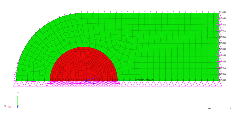
Figure 1. FE Model with Boundary Conditions and Loadcases
Benchmark Model
Hexa8 and Hexa20 elements are used to create one quarter model. The length of the sheet from left side to the center is 200mm, the inner radius of the sheet is 50mm, the outer radius of the sheet is 100mm, height of the sheet is 200mm, length of the pin is 20mm and the thickness of the sheet is 10mm. The outer surface of the pin and the inner surface of the sheet are in contact. Two equal point forces, resulting in a total force on the pin of 100kN is acting on both sides of the pin. The left side of the sheet is fixed. A frictional coefficient of 0.1 is acting between the contacts. The nodes along the pin boundary are selected as secondary nodes, while the nodes along the strip are specified to be the main nodes.
- Material Properties
- Value
- Epin
- 210 kN/mm2
- Vpin
- 0.3
- Esheet
- 70 kN/mm2
- Vsheet
- 0.3
Nonlinear Static Analysis Results
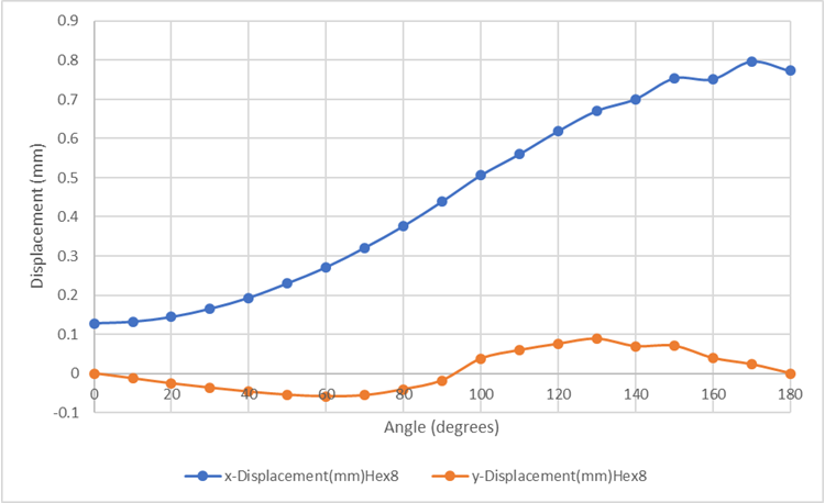
Figure 2. Displacement as a function of the angles obtained with first order elements for the nodes of the sheet contact surface
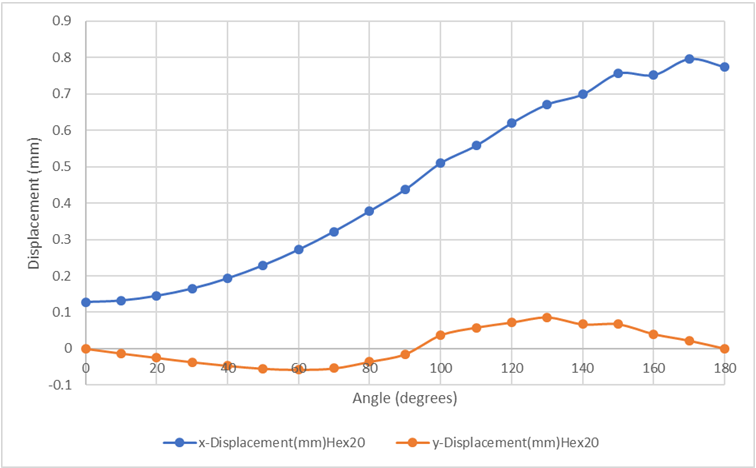
Figure 3. Displacement as a function of the angles obtained with second order elements for the nodes of the sheet contact surface
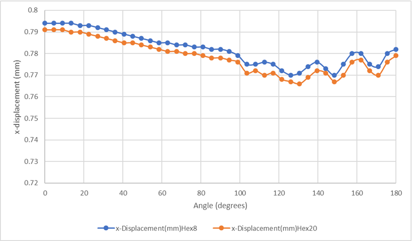
Figure 4. Displacement in x-direction for nodes along the pin as a function of the angle
Model Files
Refer to Access the Model Files to download the required model file(s).
- contb4H8.fem
- contb4H20.fem
Reference
NAFEMS R0094 - Advanced finite element contact benchmarks, Konter 2006