/PROP/TYPE45 (KJOINT2)
Block Format Keyword KJOINT2 is a penalty connection used to model joint connections between rigid or deformable bodies.
Format
| (1) | (2) | (3) | (4) | (5) | (6) | (7) | (8) | (9) | (10) |
|---|---|---|---|---|---|---|---|---|---|
| /PROP/TYPE45/prop_ID/unit_ID or /PROP/KJOINT2/prop_ID/unit_ID | |||||||||
| prop_title | |||||||||
| Type | Kn | ScF | Cr | sens_ID | Skew_ID1 | Skew_ID2 | |||
| (1) | (2) | (3) | (4) | (5) | (6) | (7) | (8) | (9) | (10) |
|---|---|---|---|---|---|---|---|---|---|
| Kti | fct_Kti | SDi- | SDi+ | Icomb_ti | |||||
| Ct | fct_Cti | ||||||||
| Kfxi | FFi | fct_FFi | |||||||
| (1) | (2) | (3) | (4) | (5) | (6) | (7) | (8) | (9) | (10) |
|---|---|---|---|---|---|---|---|---|---|
| Kri | fct_Kri | SAi- | SAi+ | Icomb_ri | |||||
| Cri | fct_Cri | ||||||||
| Kfri | FMi | fct_FMi | |||||||
Definitions
| Field | Contents | SI Unit Example |
|---|---|---|
| prop_ID | Property
identifier. (Integer, maximum 10 digits) |
|
| unit_ID | (Optional) Unit Identifier. (Integer, maximum 10 digits) |
|
| prop_title | Property
title. (Character, maximum 100 characters) |
|
| Type | Joint type (Joint Types List).
(Integer) |
|
| Kn | Stiffness for blocked DOF.
4
Default = 0.0 (Real) |
|
| ScF | Scale factor for
Kn. 4 If Kn = 0: Scale factor on both translational and rotational stiffness. Default = 1.0 (Real) If Kn > 0: Scale factor on only the rotational stiffness. Default = 10.0 (Real) |
|
| Cr | Critical damping factor.
4 Default = 0.05 (Real) |
|
| sens_ID | Sensor identifier. 3 (Integer) |
|
| Skew_ID1 | First skew system identifier . 4 (Integer) |
|
| Skew_ID2 | Second skew
system identifier. 4
(Integer) |
|
| Kti | Translational stiffness of
non-blocked DOF. 4 If fct_Kti = 0: Constant translational stiffness value. If fct_Kti > 0: Translational stiffness scale factor. Default =1.0 (Real) |
or |
| fct_Kti | Translational force versus
displacement function identifier of non-blocked
DOF. (Integer) |
|
| SDi-, SDi+ | Negative and Positive
stopping displacement. 8 Default = 0.0 (Real) |
|
| Cti | Translational viscosity
coefficient of non-blocked DOF. 4 If fct_Cti = 0: Constant translational viscosity. If fct_Cti > 0: Translational viscosity scale factor. Default = 1.0 (Real) |
or |
| fct_Cti | Translational viscous
force versus displacement rate function
identifier. (Integer) |
|
| Kfti | Elastic stiffness for
friction and stop displacement. 5 Default = 0.0 (Real) |
|
| FFi | Frictional force value.
5
Default = 0.0 (Real) |
|
| fct_FFi | Frictional force versus
displacement function identifier. (Integer) |
|
| Icomb_ti | Combining stop
displacements flag. 10
(Integer) |
|
| Kri | Rotational stiffness
coefficient of non-blocked DOF. 4 If fct_Kri = 0: Constant rotational stiffness value. If fct_Kri > 0: Rotational stiffness scale factor. Default = 1.0 (Real) |
or |
| fct_Kri | Rotational moment versus
rotational angle function identifier. (Integer) |
|
| SAi-, SAi+ | Positive and Negative
stopping angles in radians. 8 Default = 0.0 (Real) |
|
| Cri | Rotational viscosity
coefficient of non-blocked DOF. If fct_Cri = 0: Constant rotational viscosity value. If fct_Cri > 0: Rotational viscosity scale factor. Default = 1.0 (Real) |
or |
| fct_Cri | Rotational viscosity
moment versus rotational angle rate function
identifier. (Integer) |
|
| Kfri | Elastic stiffness per
radian unit for friction and stop angle. 5 Default = 0.0 (Real) |
|
| FMi | Frictional moment value of
non-blocked DOF. 5 If fct_FMi = 0: Constant frictional moment value. If fct_FMi > 0: Frictional moment scale factor. Default = 0.0 (Real) |
|
| fct_FMi | Frictional moment versus
rotational angle function identifier. (Integer) |
|
| Icomb_ri | Combining stop angles.
10
(Integer) |
Joint Types List
| Type No. | Joint Type | dx | dy | dz | |||
|---|---|---|---|---|---|---|---|
| 1 | Spherical | x | x | x | 0 | 0 | 0 |
| 2 | Revolute | x | x | x | 0 | x | x |
| 3 | Cylindrical | 0 | x | x | 0 | x | x |
| 4 | Planar | x | 0 | 0 | 0 | x | x |
| 5 | Universal | x | x | x | x | 0 | 0 |
| 6 | Translational | 0 | x | x | x | x | x |
| 7 | Oldham | x | 0 | 0 | x | x | x |
| 8 | Rigid | x | x | x | x | x | x |
| 9 | Free | 0 | 0 | 0 | 0 | 0 | 0 |
- x
- Denotes a blocked DOF
- 0
- Denotes a free (user-defined) DOF
Example (Rotational)
#RADIOSS STARTER
/UNIT/2
unit for prop
                  kg                  mm                  ms
#---1----|----2----|----3----|----4----|----5----|----6----|----7----|----8----|----9----|---10----|
/PROP/TYPE45/2/2
Revolute
### - Define angle limit < 0.52rad
### - And define friction moment 100GPa to block angle (if it reached the limit)
#     Type                  KN                 SCF                  CR  SENSORID
         2                   0                   0                   0         0
#                KR1Func_ID_Kr                SA1-                SA1+  Icomb_r1
                   0         0                   0                 .52         0
#                CR1Func_ID_Cr
                   0         0
#               KFR1                 FM1   FCT_FM1
                   0                 100         0
#---1----|----2----|----3----|----4----|----5----|----6----|----7----|----8----|----9----|---10----|
#ENDDATA
Example (Translational)
#RADIOSS STARTER
/UNIT/2
unit for prop
                  kg                  mm                  ms
#---1----|----2----|----3----|----4----|----5----|----6----|----7----|----8----|----9----|---10----|
/PROP/TYPE45/12/2
Translational
### - define displacement limit: -100mm ~ 100 mm
#     Type                  KN                 SCF                  CR  SENSORID
         6                   0                   0                  .2         0
#                KX1Func_ID_Kx                SD1-                SD1+  Icomb_t1
                   0         0                -100                 100         0
#                CX1Func_ID_Cx
                   0         0
#               KFX1                 FF1   FCT_FF1
                1000                   0         0
#---1----|----2----|----3----|----4----|----5----|----6----|----7----|----8----|----9----|---10----|
#ENDDATA
Comments
- The KJOINT2 spring is typically used to connect rigid bodies, but can also be used to connect nodes of deformable elements. When connecting nodes of deformable elements, the moment is not transferred if the node of the element does not have any rotatinal degees of freedom (DOF). This includes the following cases: all rotational DOF for nodes of solid and truss element, the drilling DOF of shell elements with the shell property Idril=2 (default), and some DOF for nodes of beam and spring elements.
- Spring element:
- The identifier must be unique in each element family, but it is advised to have a unique element identifier in the global model for each element type.
- More than one spring block can be used to define a part.
- Spring DOF:
- Joint properties are defined in a local coordinate system of the joint element.
- The total number of joint DOF computed in the local coordinate system
frame is six:
- Blocked and free DOF are distinguished for each joint type.
- The blocked DOF are characterized by a constant stiffness. By default, if no stiffness value is entered, the value of the stiffness is automatically computed to preserve the time step.
- The translational and rotational DOF are defined as:
(1) Where, and are total displacements of two joint nodes in the local coordinate system.(2) Where, and are total relative rotations of two connected body axes, with respect to the local coordinate system of the joint.
- If sens_ID is defined, then the joint becomes fully blocked (all degrees of freedom) when the sensor is activated.
- Forces and moments
calculation:
- The force in direction
is computed as:Linear spring:
(3) : translational stiffness
: translational viscosity
Nonlinear spring:(4) - The moment in
direction is computed as:Linear spring:
(5) : rotational stiffness ( )
: rotational viscosity ( )
Nonlinear spring:(6) - The joint length may be, but is not necessarily equal to 0. It is recommended to use a 0 length spring to define a spherical joint or a universal joint.
- To satisfy the global balance of moments in a general case, correction
terms in the rotational DOF are calculated as:
(7) (8) (9) Joints do not have user-defined mass or inertia, so the nodal time step is always used. The nodal time step is based on entities that the joint connects. If attached to a main node of a rigid body, the rigid body time step is used. If attached to the nodes of a deformable element, the nodal time is calculated based on the deformable element.
- The force in direction
is computed as:
- Stiffness of spring
- Coefficients and are used as constant stiffness, if there are no user-defined functions. If a function is defined, the corresponding stiffness coefficient becomes a scale factor for the function.
- If Kn = 0, the blocking stiffness is automatically computed at the beginning of the computation for both translational and rotational blocked DOF, in order to preserve the time step. These values are also selected according to the model physics and must be higher than the stiffness of the neighboring elements.
- If Kn = 0, then Scf is a scaling factor applied to both translational and rotational blocking stiffness. If Kn > 0, then Scf is applied only on blocking rotational stiffness. This parameter can be used to manually adjust the blocking stiffness in rotation.
- Viscosity of spring
- Coefficients and are used as linear viscosity coefficients, if there are no user-defined functions. If a function is defined, the corresponding coefficient becomes a scale factor for the function.
- There are two ways to introduce viscous damping:
- Defining a critical damping (for blocked DOF only):
Viscous damping is defined in terms of the critical damping factor. The critical damping coefficient is calculated using the blocking stiffness value of the element and the reduced mass (half of the harmonic mean of mass of the connected nodes). The same critical damping is applied to all blocked DOF.
- User-defined constant or nonlinear damping:
It is possible to define independent damping parameters for each free DOF.
For more information about stiffness and damping, refer to Spring Joint TYPE45 (/PROP/KJOINT2) in the User Guide.
- Defining a critical damping (for blocked DOF only):
- Friction
- Friction is not activated, if Kfti or Kfri are not defined.
- FFi and FMi are used as constant friction force and moment, if there are no user defined functions. If the friction function number is not 0, FMi and FFi become a scale factor for the functions (default = 1.0).
- Spring limit
- If a non-zero value is specified for SDi- or SDi+, then an additional penalty force is applied to prevent the displacement exceeding SDi+ for positive displacement and SDi- for negative displacement. This penalty force is computed using Kfti.
- If a non-zero value is specified for SAi- or SAi+, then an additional penalty moment is applied to prevent the angle exceeding SAi+ for positive rotation or SAi- for negative rotation. This penalty moment is computed using Kfri
- Skew of spring
- If Skew_ID1 is defined, the initial local coordinate system is defined by Skew_ID1. If Skew_ID1 = 0, the local coordinate system is computed according to the additional nodes of the spring. Refer to /SPRING for more information.
- If Skew_ID2 is defined, rotation angles of
the joint are initialized according the rotation between Skew_ID1 and
Skew_ID2.
Values of the initial angles can be check in the Starter output file.
For revolute (TYPE2), cylindrical (TYPE3) and planar (TYPE4) joints only
can be initialized. The first axis of
Skew_ID1 and
Skew_ID2 must
be parallel.
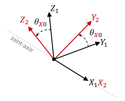
Figure 1. Computation of Initial Rotation Angle for Revolute Joint (TYPE2) - If Skew_ID2 is non-zero and Skew_ID1 =0, then Skew_ID1 is the global coordinate system.
- The local coordinate system orientation is updated according to node_ID1 (/SPRING) rotation.
- Combined stop
displacements/angles:
- If Icomb_ti = 0: the stop displacements are independent (default) as shown in Figure 2. Stop displacement will be checked separately in each direction.
- If Icomb_ti = 1: the stop displacements of all the free translational DOF are combined. The stopping criteria is no longer applied on the displacement but on the normal of the combined displacements see Figure 3.
- 2 or 3 stop displacements can be combined
- If stop displacements are combined, the same value of SDi- and SDi+ must be used for each DOF.
- The above descriptions for stop displacements also apply for stop angles
defined using
Icomb_ri.
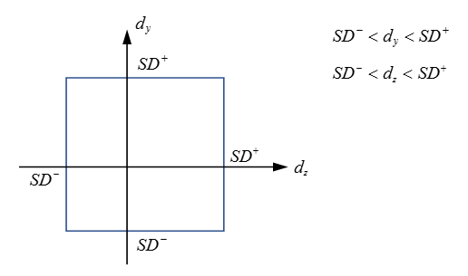
Figure 2. Planar Joint with Independent Stop Displacements, Icomb_ti=0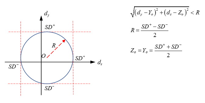
Figure 3. Planar Joint with 2 Combined Stopping Displacements, Icomb_ti=1