/RWALL/THERM
Block Format Keyword Describes the ALE rigid wall.
Format
| (1) | (2) | (3) | (4) | (5) | (6) | (7) | (8) | (9) | (10) |
|---|---|---|---|---|---|---|---|---|---|
| /RWALL/THERM/wall_ID | |||||||||
| wall_title | |||||||||
| (1) | (2) | (3) | (4) | (5) | (6) | (7) | (8) | (9) | (10) |
|---|---|---|---|---|---|---|---|---|---|
| Slide | grnd_ID1 | grnd_ID2 | |||||||
| Dsearch | fric | ||||||||
| XM | YM | ZM | |||||||
| XM1 | YM1 | ZM1 | |||||||
| fct_IDT | FscaleT | R | |||||||
Definitions
| Field | Contents | SI Unit Example |
|---|---|---|
| wall_ID | Rigid wall
identifier. (Integer, maximum 10 digits) |
|
| wall_title | Rigid wall
title. (Character, maximum 100 characters) |
|
| Slide | Sliding flag.
(Integer) |
|
| grnd_ID1 | Node group defining
secondary nodes to be added to the rigid
wall. (Integer) |
|
| grnd_ID2 | Node group defining
secondary nodes to be deleted from the rigid
wall. (Integer) |
|
| Dsearch | Distance for secondary
node search. (Real) |
|
| fric | Friction. (Real) |
|
| Diameter. (Real) |
||
| XM | X coordinate of
M. (Real) |
|
| YM | Y coordinate of
M. (Real) |
|
| ZM | Z coordinate of
M. (Real) |
|
| XM1 | X coordinate of
M1. (Real) |
|
| YM1 | Y coordinate of
M1. (Real) |
|
| ZM1 | Z coordinate of
M1. (Real) |
|
| fct_IDT | Wall temperature
function. (Integer) |
|
| FscaleT | Wall temperature scale
factor. (Real) |
|
| R | Thermal resistance R = d /
K.
(Real) |
Comments
- Only the plane type of rigid wall is available
for /RWALL/THERM. Coordinate of M and M1 are used to define
the normal of the plane.
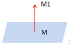
Figure 1. - The first input format used to define the rigid wall is the coordinates of point M, at the location of the rigid wall.
- The second input is the coordinates of point M1, defining the outward normal direction of the wall.
- The secondary nodes can be defined as a list of nodes and/or as the nodes initially at a distance less than Dsearch from the wall.