L2 Card
This L2 card places a load (complex impedance) on a node.
On the Source/Load tab, in the Loads /
networks group, click the ![]() Load icon. From the drop-down list, click the
Load icon. From the drop-down list, click the ![]() Vertex load (L2) icon.
Vertex load (L2) icon.
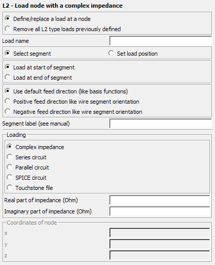
Figure 1. The L2 - Load node with a complex impedance dialog.
Parameters:
- Define/replace a load at a node
- Define a load with the following parameters.
- Remove all L2 type loads previously defined
- This L2 card does not define a load, but rather all previously defined L2 loads are deleted. All the other input parameters of this card are ignored.
- Load name
- The name of the load.
- Select segment
- When this item is selected, then the Segment label text box becomes active. This text box specifies the label of the segment which shall be loaded (either start or end point as determined by the corresponding check box). The load has to be located at a node, either between two segments, or between a segment and a triangle, ground plane or polygonal plate. Only one segment with this label should be declared. If there is more than one segment with this label then all the corresponding segment vertices will be loaded.
- Set load position
- When this check box is activated, then the load node is determined by specifying its Cartesian coordinates in the Coordinates of node group. These values are in m and may be scaled by the SF card.
- Load at start of segment
- This option is only available when selecting the feed segment by label. If set, it indicates that the load location is at the start of the wire segment with a matching label.
- Load at end of segment
- This option is only available when selecting the feed segment by label. If set, it indicates that the load location is at the end of the wire segment with a matching label.
- Use default feed direction (like basis function)
- This option is only available when selecting the feed segment by label. If set, it indicates that the positive feed direction is according to the basis function setup in Feko. For wire/surface junctions (UTD plates, infinite ground, or meshed triangle surfaces), this direction is away from the wire onto the surface. For wire connections between two segments, this direction is from the segment with the lower index to the segment with the higher index.
- Positive feed direction like wire segment orientation
- This option is only available when selecting the feed segment by label. If set, then the positive feed direction is according to the orientation of the wire segment with the specified label.
- Negative feed direction like wire segment orientation
- This option is only available when selecting the feed segment by label. If set, then the positive feed direction is opposite to the orientation of the wire segment with the specified label.
- Loading
-
- Complex impedance
- Define the real and imaginary parts of the complex impedance in Ohm using Real part of impedance (Ohm) and Imaginary part of impedance (Ohm) respectively.
- Series circuit
- The resistor value in Ohm, inductor value in Henry and the capacitor value in Farad to be added as a series circuit.
- Parallel circuit
- The resistor value in Ohm, inductor value in Henry and the capacitor value in Farad to be added as a parallel circuit.
- SPICE circuit
- Specify the name of a one-port SPICE circuit to define a load between two pins. Define the SPICE circuit using the SC card.
- Touchstone file
- Specify a one-port Touchstone file (.s1p,
.z1p, .y1p) to define a load.Note: If the load is added to a port that has a voltage source, the load is placed in series with the voltage source.