LZ Card
This card can be used to assign a complex impedance to a segment.
On the Source/Load tab, in the Loads /
networks group, click the ![]() Load icon. From the drop-down list, click the
Load icon. From the drop-down list, click the ![]() Complex load (LZ) icon.
Complex load (LZ) icon.
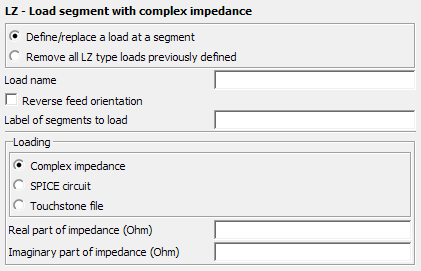
Figure 1. The LZ - Load segment with complex impedance dialog.
Parameters:
- Define/replace a load at a segment
- Define a load with the following parameters.
- Remove all LZ type loads previously defined
- This LZ card does not define a load, but rather all previously defined LZ loads are deleted. All the other input parameters of this card are ignored.
- Load name
- The name of the load.
- Reverse feed orientation
- By default, the vector of the voltage is orientated in the direction from the start of the segment to its end (the direction in which it was created). When this option is checked, the vector of the voltage is orientated in the opposite direction. This is the direction of the current flow through the segment. The internal EMF (electromotive force) of the impressed voltage source is in the opposite direction.
- Label of segments to load
- All segments with this label are assigned the complex circuit values specified below.
- Complex impedance
- The real and imaginary part of the complex impedance in .
- SPICE circuit
- Specify the name of a one-port SPICE circuit to define a load between two pins. Define the SPICE circuit using the SC card.
- Touchstone file
- Specify a one-port Touchstone file (.s1p,
.z1p, .y1p) to define a load.Note: If the load is added to a port that has a voltage source, the load is placed in series with the voltage source.
The complex impedance value is a constant with respect to frequency. Frequency dependent impedances can be realised using the LS or the LP cards.
The LZ card may be combined with the LD, LP, LS and the SK cards, but only one LZ card may be used per label. If a second LZ card is used, it replaces the values entered by the first one. This card has no significance for surface elements, even when these are assigned the same label.