PW Card
The PW card specifies the radiated power or the source power. It can also be used to consider mismatch.
On the Source/Load tab, in the Settings
group, click the ![]() Power (PW)
icon.
Power (PW)
icon.
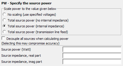
Figure 1. The PW - Specify the source power dialog.
Parameters:
- No scaling (use specified voltages)
- PW card is not activated meaning the specified value of the voltage or current source is used.
- Total source power (no internal impedance)
- The PW card is active and the entire solution is scaled by a scaling factor so that the total source power (the sum of the power delivered by all the individual sources) is P0 — the value specified in the Source power (Watt) field. Mismatch is not considered.
- Total source power (internal impedance)
- All voltage and/or current sources are assumed to have an internal impedance
Zi as specified by the parameters Source impedance, real
part and Source impedance, imag part. The solution
coefficients are scaled such that the total power supplied by the sources equals
P0 as discussed below. The mismatch loss in the source internal impedance
reduces the antenna gain. Note: The solution coefficients, for example, refers to the current coefficients for surface triangles in a MoM or PO solution. These can also refer to the electric field coefficients in a FEM solution.
- Total source power (transmission line feed)
- All the antennas are assumed to be fed by transmission lines with a complex characteristic impedance ZL as specified by the parameters Charact. impedance, real part and Charact. impedance, imag part. If there is a mismatch between ZL and the antenna input impedance Za, a fraction of the incident power will be reflected back to the source.
- Decouple all sources when calculating power
- When this item is not checked and multiple impressed sources (that is, elementary dipoles with the A5/A6 cards, or impressed current elements with the AI/AV cards, and so forth) are present, the mutual coupling of all these sources, as well as the coupling of the sources with other structures such as ground (BO card), UTD surfaces, or MoM elements are taken into account when determining the source power. This is also the default if the PW card is not present. However, when this item is checked the mutual coupling is not considered. Ignoring the mutual coupling is acceptable when sources are spaced far apart or when accurate power values are not required. (Since gain and directivity are based on power, these values are then also possibly not very accurate.)
- Source power
- The total power P0 in Watt supplied by all the voltage and/or current sources. In the case of transmission lines it is the total power of all forward travelling waves.
Details of the various possibilities with the use of the PW card are shown below.

Figure 2. Possible applications of the PW card to determine the total power.
The options Total source power (internal impedance) and Total source power (transmission line feed) are allowed for voltage sources (the A1, A2, A3, A7, AE and AN cards) and the current source (AF card) which is used in a FEM dielectric. For models containing other sources such as elementary dipoles and impressed currents (AI, AV and AC cards), the option Total source power (no internal impedance) should be used. For plane waves No scaling (use specified voltages) should be used.
The power equations for different cases are discussed below. Consider, in general, that there are N voltage and/or current sources (such as in an array antenna) with open circuit voltages and short circuit currents (before the scaling operation) where the parameter is in the range 1. . .N. At each source there is an antenna input impedance (as calculated during the Feko solution) to which power is transferred.
- Total source power (no internal impedance):
Using this option all the source power is delivered to the respective antennas, that is
as shown in the top left of the figure. To ensure that the total power is P0, the power must be scaled with the factor(1) (2) The currents on the structure are consequently scaled with the factor . There is no power loss.
- Total source power (internal impedance):
When this option is used the internal impedance Zi of the voltage or current source is considered as shown in the top right and bottom left of the figure.
For voltage sources the same current flows through the internal source impedance and the antenna input impedance. For the current source (AF card) the same voltage is applied across the internal source impedance and the antenna input impedance.
The power dissipated in the impedance of the voltage source is given by the relation
(3) The power dissipated in the impedance of the current source is given by the relation
(4) The scaling factor S (to scale the total power supplied by the voltage and or current sources to P0) is
(5) The combined loss caused by the mismatched antennas,
reduces, for example, the antenna gain (but not the directivity).(6) - Total source power (transmission line feed):
When this option is used each antenna (with input impedance ) is considered to be excited by a transmission line with a complex characteristic impedance ZL as shown in the bottom right figure. For most practical applications the transmission line will be lossless, resulting in a real characteristic wave impedance. For this lossless case the reflection factor is
is taken into account when calculating the incident power at the feed point.(7) The total incident power for the nth source is given by
and the reflected power by(8) (9) To ensure that the total incident power is P0, the power is scaled with the factor
and the currents with the factor . As before the total reflected power(10) reduces the gain of the antenna.(11)