Calibration factors
1. Overview - Definitions
| Label | Symbol | Tooltip, note, formula |
| Resistance factor | * | Setting of the “Resistance factor”: It allows modifying the computation
result of resistance. Thus, the resulting phase resistance value is considered. |
| Inductance factor | * | Setting of the “Inductance factor”. It allows modifying the computation
result of end-winding inductance. Thus, the resulting end-winding inductance value is considered. |
| Ref. temperature | * | The reference temperature: First, the resistance values are computed by
considering a temperature equal to 20°C. However, the user can also define his own reference temperature to compute the corresponding phase resistance and Line-Line resistance values. Note: This reference temperature is used only in the
winding design environment.The test temperatures are defined in the test
settings (refer to TEST chapter).
|
2. Illustrations
 |
|
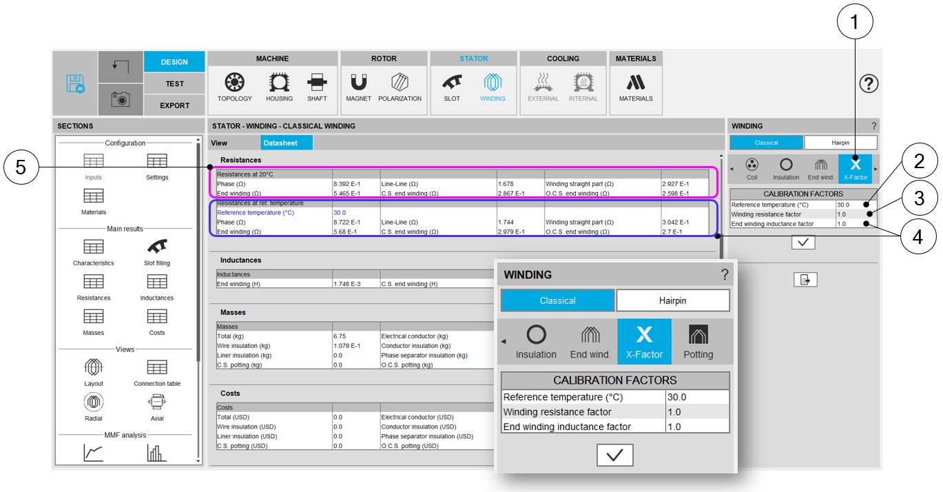
| Building the winding – X-Factor = Calibration factors | |
| 1 | Selection of the X-FACTOR section. |
| 2 | Setting of the “Resistance factor”. It allows adjusting computation
result of resistance. Thus, the resulting phase resistance value is considered. |
| 3 | Setting of the “Inductance factor”. It allows modifying the computation
result of end-winding inductance. Thus, the resulting end-winding inductance value is considered. |
| 4 | The reference temperature: First, resistance values are computed by considering a temperature equal to 20°C (5). However, the users can also define their own reference temperature to compute the corresponding phase resistance and Line-Line resistance values. |
| 5 | Resistance values for a reference temperature equal to 20°C. |