Browsers supply a great deal of view-related functionality by listing the parts of a model in a tabular and/or tree-based
format, and providing controls inside the table that allow you to alter the display of model parts.
FE geometry is topology on top of mesh, meaning CAD and mesh exist as a single entity. The purpose of FE geometry
is to add vertices, edges, surfaces, and solids on FE models which have no CAD geometry.
Tools and workflows that are dedicated to rapidly creating new parts for specific use cases, or amending existing
parts. The current capabilities are focused on stiffening parts.
Create and edit systems, assemblies, and analyses, use wizards to build models quickly, create and edit belt/pullies,
NLFE stabars, and NLFE springs, access the EDEM and Track Builder tools.
Create and edit points, bodies, lines (curve graphics), solids (graphics), markers and vectors, edit grounded/ungrounded
bodies, create and edit rigid body groups, configure gravity, and select material properties.
Use the Points tool to create and edit
individual points, points on a vector, points along a curve, points at
the center of a circle, and parametric points.
In a multibody system, a rigid body is an ideal representation of solid body/part of fixed size and shape in which
deformation is insignificant or neglected, or in other words, the distance between any two points of a rigid body
remains unchanged (irrespective of the external forces acting on it). A rigid body will have six degrees of freedom
(DOF) and therefore every additional rigid body in a multibody system adds an additional six DOF to the system.
Deformable bodies (also called Flex bodies) in multibody systems are those that can be used to model elastic deformation
of the bodies of the system. The deformable body connects to its neighboring elements/bodies through interface nodes.
The deformable body consists of reduced stiffness and mass matrices, which can be obtained in various ways. Two
popular methods for the same are: Craig-Bampton Method and Craig-Chang Method.
The point mass body is a reduced version of the six DOF rigid body. It only has three translational DOFs, therefore
the point mass body has mass but no inertia properties. The position of a point mass is defined by a center of mass
point. By default, the orientation of the point mass is set to be the same as the Global Coordinate System (which
never changes during simulation). The purpose of a point mass entity is to add additional representative weight
to another body, for example the mass of a driver on a seat.
NLFE stands for Non Linear Finite Elements. The NLFE implementation in HyperWorks/MotionSolve is based on Absolute Nodal Coordinate Formulation or ANCF. In this approach, only absolute coordinates and global
slopes are used to define the element nodal coordinates without the need for using infinitesimal or finite rotations.
In complex multi-body simulations, flexible bodies are needed to improve model fidelity. In cases where the deformations
and rotations are expected to be large and/or exceed linear assumptions, NLFE becomes a necessity.
Use the tool to create curve graphics from a set of selected
points or nodes. The generated curve graphics can be used to setup 2D
rigid to rigid contact or advanced joints, such as point to curve or
curve to curve joints. Based on the selected set of points or nodes
belonging to a file graphic or CAD graphic, this tool creates a 3D
cartesian curve and a curve graphic.
Create and edit outputs, create and edit templates, run the solver, view reports, access the Load Export utility,
use the Optimization Wizard, open HyperStudy, utilize many pre-processing and post-processing capabilities with regards
to flexible bodies (or flexbodies), run MS/EDEM cosimulation in batch mode, and generate H3D from EDEM.
Create and edit points, bodies, lines (curve graphics), solids (graphics), markers and vectors, edit grounded/ungrounded
bodies, create and edit rigid body groups, configure gravity, and select material properties.
NLFE stands for Non Linear Finite Elements. The NLFE implementation in HyperWorks/MotionSolve is based on Absolute Nodal Coordinate Formulation or ANCF. In this approach, only absolute coordinates and global
slopes are used to define the element nodal coordinates without the need for using infinitesimal or finite rotations.
In complex multi-body simulations, flexible bodies are needed to improve model fidelity. In cases where the deformations
and rotations are expected to be large and/or exceed linear assumptions, NLFE becomes a necessity.
Generating Position and Gradients for Loaded Configuration
The following process can be used to generate a CSV file
containing the position and gradients for loaded configuration, which can then be
imported and saved into a MotionView model.
Start with the NLFE Body in a No Load configuration and apply Force/Motion to
load the NLFE Body as needed.
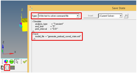
Include the MotionSolve Save command to save the states of the model into an
XML file (herein referred as “saved state XML”) after the Simulate command. A
template that writes into the solver command section can be used in MotionView.
Figure 1.
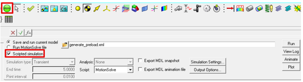
Solve the model. From the MotionView Run panel, use the Scripted simulation
option.
Figure 2.
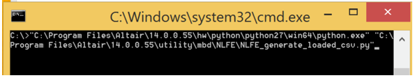
Use a python script “NLFE_generate_loaded_csv.py” available in the Hyperworks
install (install_location/utility/mbd/NLFE) to extract the final loaded state of
the NLFE Body and save it into a CSV file. The python executable “python.exe”
(if not installed separately) can also be found in the Hyperworks install
(install_location/hw/python\python27\win64).
Figure 3.
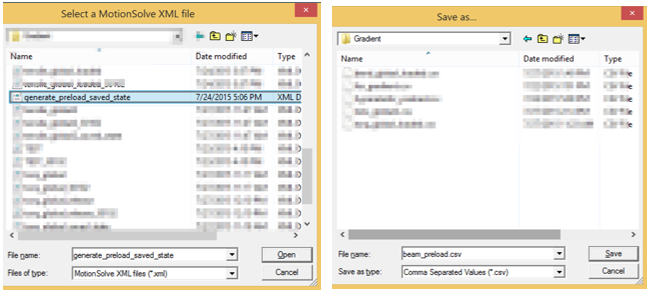
The script will prompt you to open the saved state XML file and also
provide a CSV file name to save the position and gradients information.Figure 4.
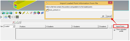
Once the CSV file is saved, import it into MotionView using the Import Points
option available in the Loaded View of the NLFE Connectivity tab.
Figure 5.
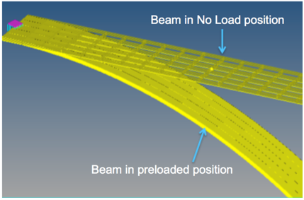
Upon importing the loaded configuration, the display of the NLFE Body in
graphics area would change. The NLFE Body loaded configuration gets the
prominent display with solid implicit graphics while the no load configuration
will be shown in a wireframe featured mode. Figure 6.