There are three approaches to building an SEA subsystem:
Import CAD geometry.
Import an FE model.
Use geometric entities.
In SEAM, a dynamic system is separated into a series of
structural and acoustic elements. In the SEA analysis procedure, these elements are
separated even further into SEA subsystems. A certain number of subsystems, or mode
groups, are needed to completely describe the response of an element. However, in
some cases, the loading and/or boundary conditions on a particular element justify
the omission of certain standard subsystems and the addition of more complex
subsystems in the analysis.
An SEA subsystem can be created using each specific option. Once a subsystem is
created, you can assign properties and materials, which are created and
assigned.
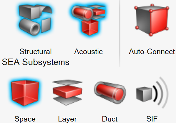
There are eight types of basic elements. Each icon in the SEAM ribbons corresponds to a different element type. These
elements are categorized as structural and
acoustic elements.
Structural
Plate
Shell
Beam
Pipe
Frame
Figure 1. Structural Elements
Acoustic
Acoustic space (3D)
Acoustic layer (2D)
Acoustic duct (1D)
Acoustic SIF (3D)
Figure 2. Acoustic Elements
Create and Edit a Plate
A plate is a two-dimensional, flat panel structural element that supports bending and
inplane deformation modes.
From the Model ribbon > SEA Subsystems group, click the Structural icon, followed
by the Plate tool.
Figure 3.
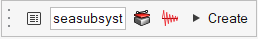
Create a plate:
Left-click in the modeling window to select a point or node until you
are able to create a plate.
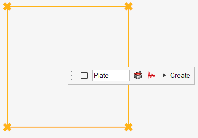
After selecting more than two points, a guidebar is displayed that you
can use to assign properties, , and damping, .
Figure 4.
Figure 5. Figure 6.
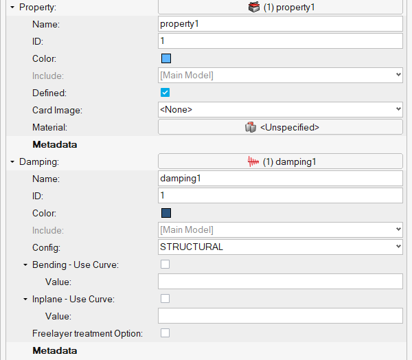
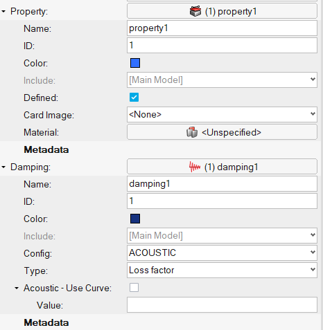
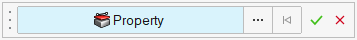
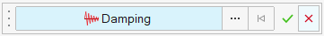
Specify the plate name in the name field.
Click and assign properties and damping,
respectively.
Click Create to create a plate.
Figure 7.
The required parameters to create the plate subsystem are
updated.
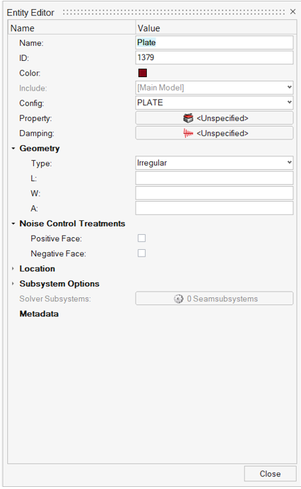
Right-click on Plate to edit the subsystem and update
the parameters.
Figure 8. Figure 9. Plate Entity Editor
Name
Specify a unique name.
ID
Specify a unique ID.
Config
Specify the element type.
Property
Specify the property parameter based on the element type.
Damping
Specify damping to the subsystem.
Geometry
Based on the element type, update geometry parameters.
Subsystem Options
For experienced users, expand the Subsystem Options to change the
default choices for the SEA Subsystems for all element types. For
certain structural element types, use these options to adjust the
default bending stiffness or conductance of the element and add
non-structural mass, component mass, or fluid loading to the element
when the options have been changed.
Damping
Assign a damping model to the element. From the Damping field
drop-down menu, select a damping model. This list contains all
predefined models which apply to the current element type. Click
to display advanced damping options
that you can use to define additional damping models.
Properties
Assign a property model to the element. From the Property field
drop-down menu, select a property model. The element materials and
cross-sectional parameters defined in the selected Property record
are displayed. Property records can be used to simplify the model
definition in cases where many elements have the same properties.
Click to display advanced property options
that you can use to define additional property models.
Figure 10.
Create and Edit Space
Space is a three-dimensional, acoustic element supporting acoustic modes.
From the Model ribbon > SEA Subsystems group, click the Acoustic icon, followed
by Space tool.
Figure 11.
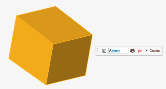
Create space.
Click a Surface, Plate,
or Shell subsystem. If all subsystems or surfaces
make it a closed entity, then it creates a cavity.
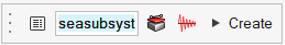
Once you select a proper closed entity, a guidebar is displayed that
you can use to assign properties, , and damping, .
Figure 12.
Figure 13. Figure 14.
Specify the space name in the field.
Click and assign properties and damping,
respectively.
Click Create to create space.
Figure 15.
The required parameters to create a space subsystem are updated.
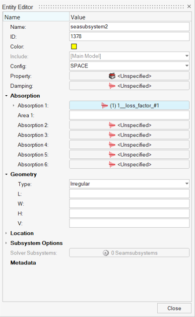
Right-click on space to edit the subsystem and update the parameters.
Figure 16.
Figure 17. Space Entity Editor
Name
Specify unique name.
ID
Specify unique ID.
Config
Specify the element type.
Property
Specify the property parameter based on the element type.
Damping
Specify damping to the subsystem.
Absorption 1
Define or select the absorption entity and define the area about
it.
Geometry
Based on the element type, update geometry parameters.
Subsystem Options
For experienced users, expand the Subsystem Options to change the
default choices for the SEA Subsystems for all element types. For
certain structural element types, use these options to adjust the
default bending stiffness or conductance of the element and add
non-structural mass, component mass, or fluid loading to the element
when the options have been changed.
Damping
Assign a damping model to the element. From the Damping field
drop-down menu, select a damping model. This list contains all
predefined models which apply to the current element type. Click
to display advanced damping options
that you can use to define additional damping models.
Properties
Assign a property model to the element. From the Property field
drop-down menu, select a property model. The element materials and
cross-sectional parameters defined in the selected Property record
are displayed. Property records can be used to simplify the model
definition in cases where many elements have the same properties.
Click to display advanced property options
that you can use to define additional property models.
Figure 18.
Create and Edit a Semi Infinite Fluid (SIF)
An acoustic element represents the infinite propagation medium for an exterior
radiation scenario/problem. It can be attached to multiple acoustic subsystems to
transfer the energy. The acoustic connections automatically consider the propagating
surface area for connections. This element automatically creates semi-infinite
acoustic space and connects the exterior-most acoustic space that you select.
From the Model ribbon > SEA Subsystems group, click the Acoustic tool, followed
by SIF tool.
Figure 19.
Create SIF.
From the Entity selector, click an Acoustic space subsystem, which
needs to be connected to a SIF.
Click Create.
Figure 20.
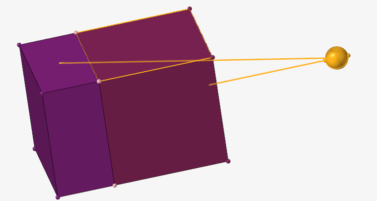
After clicking Create, a Semi-infinite Acoustic Space 3D
element is created with connecting acoustic space subsystems, which were
selected in the previous step using the acoustic connections.
The exterior surface of the acoustic space is considered for the acoustic
connection's area.
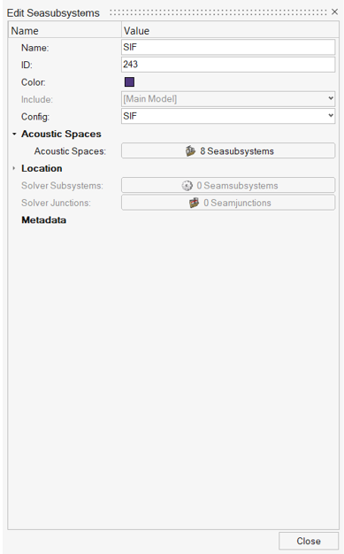
Right-click SIF to edit the subsystem and update the parameters.
Figure 21. SIF element represented, with its connections Figure 22.
Name
Specify a unique name.
Unique ID
Specify a unique ID.
Config
The element type.
Acoustic Spaces
Specify the acoustic space to connect. Update the entities to add or
remove.
Create and Edit a Layer
A layer is a two-dimensional acoustic element that supports acoustic modes.
From the Model ribbon > SEA Subsystems group, click the Acoustic icon, followed
by the Layer tool.
Figure 23.
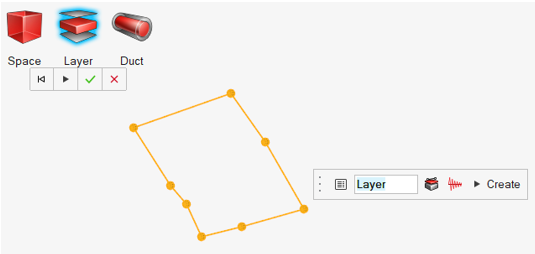
Create a layer.
Left-click in the modeling window to select a point or node until you
are able to create a layer.
After selecting more than two points, a guidebar is displayed that you
can use to assign properties, , and damping, .
Figure 24.
Figure 25. Figure 26.
Specify the name in the field.
Click and assign properties and damping,
respectively.
Click Create to create a layer.
Figure 27.
The required parameters to create the layer subsystem are
updated.
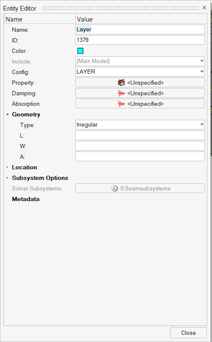
Right-click on Layer to edit the subsystem and update
the parameters.
Figure 28.
Figure 29. Layer Entity Editor
Name
Specify unique name.
ID
Specify unique ID.
Config
Specify the element type.
Property
Specify the property parameter based on the element type.
Damping
Specify damping to the subsystem.
Absorption 1
Define or select the absorption entity and define the area about
it.
Geometry
Based on the element type, update geometry parameters.
Subsystem Options
For experienced users, expand the Subsystem Options to change the
default choices for the SEA Subsystems for all element types. For
certain structural element types, use these options to adjust the
default bending stiffness or conductance of the element and add
non-structural mass, component mass, or fluid loading to the element
when the options have been changed.
Damping
Assign a damping model to the element. From the Damping field
drop-down menu, select a damping model. This list contains all
predefined models which apply to the current element type. Click
to display advanced damping options
that you can use to define additional damping models.
Properties
Assign a property model to the element. From the Property field
drop-down menu, select a property model. The element materials and
cross-sectional parameters defined in the selected Property record
are displayed. Property records can be used to simplify the model
definition in cases where many elements have the same properties.
Click to display advanced property options
that you can use to define additional property models.
Figure 30.
Create and Edit a Duct
A duct is a one-dimensional acoustic element that supports acoustic modes.
From the Model ribbon > SEA Subsystems group, click the Acoustic icon, followed
by the Duct tool.
Figure 31.
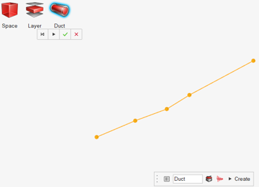
Create a duct.
Left-click in the modeling window to select a point or node until you
are able to create a duct.
After selecting more than two points, a guidebar is displayed that you
can use to assign properties, , and damping, .
Figure 32.
Figure 33. Figure 34.
Specify the duct name in the field.
Click and assign properties and damping,
respectively.
Click Create to create a duct.
Figure 35.
The required parameters to create the duct subsystem are updated.
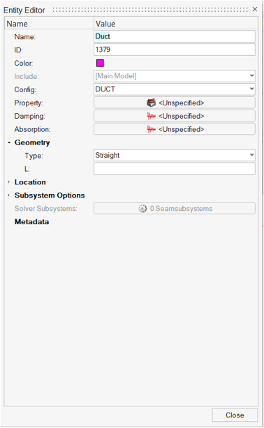
Right-click on a Duct to edit the subsystem and update
the parameters.
Figure 36.
Figure 37. Duct Entity Editor
Name
Specify unique name.
ID
Specify unique ID.
Config
Specify the element type.
Property
Specify the property parameter based on the element type.
Damping
Specify damping to the subsystem.
Absorption 1
Define or select the absorption entity and define the area about
it.
Geometry
Based on the element type, update geometry parameters.
Subsystem Options
For experienced users, expand the Subsystem Options to change the
default choices for the SEA Subsystems for all element types. For
certain structural element types, use these options to adjust the
default bending stiffness or conductance of the element and add
non-structural mass, component mass, or fluid loading to the element
when the options have been changed.
Damping
Assign a damping model to the element. From the Damping field
drop-down menu, select a damping model. This list contains all
predefined models which apply to the current element type. Click
to display advanced damping options
that you can use to define additional damping models.
Properties
Assign a property model to the element. From the Property field
drop-down menu, select a property model. The element materials and
cross-sectional parameters defined in the selected Property record
are displayed. Property records can be used to simplify the model
definition in cases where many elements have the same properties.
Click to display advanced property options
that you can use to define additional property models.
Figure 38.
Create and Edit a Shell
A shell is a two-dimensional flat panel structural element that supports bending and
inplane deformation modes.
From the Model ribbon > SEA Subsystems group, click the Structural icon, followed
by the Shell tool.
Figure 39.
Create a shell.
Left-click in the modeling window to select a point or node until you
are able to create a shell.
After selecting more than two points, a guidebar is displayed that you
can use to assign properties, , and damping, .
Figure 40.
Figure 41. Figure 42.
Specify the name in the dialog.
Click and assign properties and damping,
respectively.
Click Create to create a shell.
Figure 43.
The required parameters to create the shell subsystem are
updated.
Right-click on Shell to edit the subsystem and then
update the parameters
Figure 44.
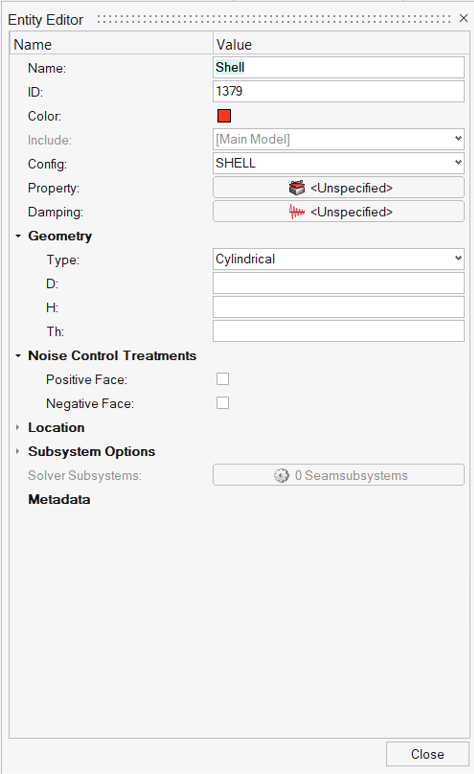
Figure 45. Shell Entity Editor
Name
Specify unique name.
ID
Specify unique ID.
Config
Specify the element type.
Property
Specify the property parameter based on the element type.
Damping
Specify damping to the subsystem.
Geometry
Based on the element type, update geometry parameters.
Subsystem Options
For experienced users, expand the Subsystem Options to change the
default choices for the SEA Subsystems for all element types. For
certain structural element types, use these options to adjust the
default bending stiffness or conductance of the element and add
non-structural mass, component mass, or fluid loading to the element
when the options have been changed.
Damping
Assign a damping model to the element. From the Damping field
drop-down menu, select a damping model. This list contains all
predefined models which apply to the current element type. Click
to display advanced damping options
that you can use to define additional damping models.
Properties
Assign a property model to the element. From the Property field
drop-down menu, select a property model. The element materials and
cross-sectional parameters defined in the selected Property record
are displayed. Property records can be used to simplify the model
definition in cases where many elements have the same properties.
Click to display advanced property options
that you can use to define additional property models.
Figure 46.
Create and Edit a Beam
A BEAM is a one-dimensional structural element with a constant cross-section that
supports bending, torsional, longitudinal, and higher-order, cross-sectional
deformation modes.
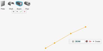
From the Model ribbon > SEA Subsystems group, click the Structural icon, followed
by the Beam tool.
Figure 47.
Create a beam.
Left-click in the modeling window to select a point or node until you
are able to create a beam.
After selecting more than two points, a guidebar is displayed that you
can use to assign properties, , and damping, .
Figure 48.
Figure 49. Figure 50.
Specify the name in the field.
Click and assign properties and damping,
respectively.
Click Create to create a beam.
Figure 51.
The required parameters to create the beam subsystem are updated.
Right-click on beam to edit the subsystem and update the
parameters.
Figure 52.
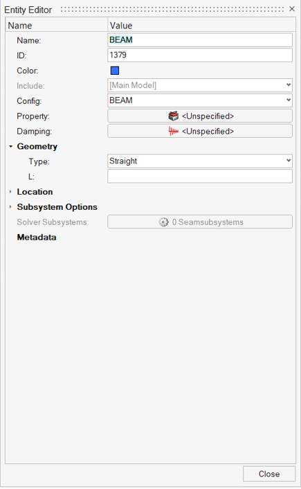
Figure 53. Beam Entity Editor
Name
Specify unique name.
ID
Specify unique ID.
Config
Specify the element type.
Property
Specify the property parameter based on the element type.
Damping
Specify damping to the subsystem.
Geometry
Based on the element type, update geometry parameters.
Subsystem Options
For experienced users, expand the Subsystem Options to change the
default choices for the SEA Subsystems for all element types. For
certain structural element types, use these options to adjust the
default bending stiffness or conductance of the element and add
non-structural mass, component mass, or fluid loading to the element
when the options have been changed.
Damping
Assign a damping model to the element. From the Damping field
drop-down menu, select a damping model. This list contains all
predefined models which apply to the current element type. Click
to display advanced damping options
that you can use to define additional damping models.
Properties
Assign a property model to the element. From the Property field
drop-down menu, select a property model. The element materials and
cross-sectional parameters defined in the selected Property record
are displayed. Property records can be used to simplify the model
definition in cases where many elements have the same properties.
Click to display advanced property options
that you can use to define additional property models.
Figure 54.
Create and Edit a Pipe
A pipe is a one-dimensional structural element with a constant cross-section that
supports bending, torsional, longitudinal, and higher-order, cross-sectional
deformation modes.
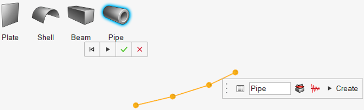
From the Model ribbon > SEA Subsystems group, click the Structural icon, followed
by the Pipe tool.
Figure 55.
Create a pipe.
Left-click in the modeling window to select a point or node until you
are able to create a pipe.
After selecting more than two points, a guidebar is displayed that you
can use to assign properties, , and damping, .
Figure 56.
Figure 57. Figure 58.
Specify the name in the field.
Click and assign properties and damping,
respectively.
Click Create to create a pipe.
Figure 59.
The required parameters to create the pipe subsystem are updated.
Right-click on pipe to edit the subsystem and update the
parameters.
Figure 60.
Figure 61. Pipe Entity Editor
Name
Specify unique name.
ID
Specify unique ID.
Config
Specify the element type.
Property
Specify the property parameter based on the element type.
Damping
Specify damping to the subsystem.
Geometry
Based on the element type, update geometry parameters.
Subsystem Options
For experienced users, expand the Subsystem Options to change the
default choices for the SEA Subsystems for all element types. For
certain structural element types, use these options to adjust the
default bending stiffness or conductance of the element and add
non-structural mass, component mass, or fluid loading to the element
when the options have been changed.
Damping
Assign a damping model to the element. From the Damping field
drop-down menu, select a damping model. This list contains all
predefined models which apply to the current element type. Click
to display advanced damping options
that you can use to define additional damping models.
Properties
Assign a property model to the element. From the Property field
drop-down menu, select a property model. The element materials and
cross-sectional parameters defined in the selected Property record
are displayed. Property records can be used to simplify the model
definition in cases where many elements have the same properties.
Click to display advanced property options
that you can use to define additional property models.


 , and damping,
  .
.
 to display advanced damping options
that you can use to define additional damping models.
to display advanced damping options
that you can use to define additional damping models.