Stiffener
Check rules of stiffener.
Components disposed on FPCB use the reinforcement plate, stiffener, in order to compensate for the thickness of the component or to protect the component as safe in SMT process.
Stiffener Layer Definition
Define stiffener layer.
- For Stiffener Top Layer, select the stiffener top layer from layer list.
- For Stiffener Bottom Layer, select the stiffener bottom layer from layer list.
Target Component Definition
Define target components.
Checking
Define checking items.
-
Select Clearance between Component Stiffener and Component’s
Pad to check the clearance between component’s stiffener and
component’s pads.
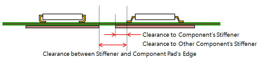
Figure 1.- Additional Void-Checking Component Selection: Add new additional void-checking component group by selecting component group from list.
-
Select Check Stiffener’s Rounding in Corners to check
whether stiffener corners’ rounding.
To check a sharp angle, use the radius in corner.
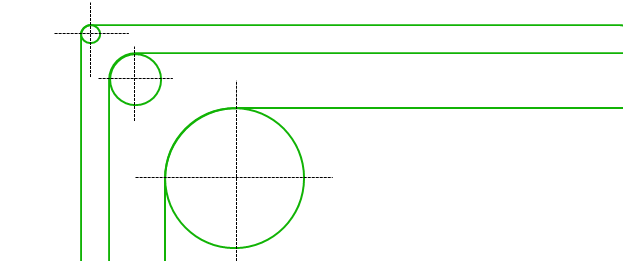
Figure 2.- Minimum Radius for Stiffener’s Angle: Set the minimum radius values.
-
Select Minimum Overlapping Width between Top and Bottom
Stiffener if there are top and bottom stiffeners at same area to
check the overlapping width.
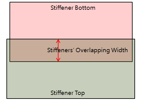
Figure 3. -
Select Check Existence of String for Stiffener’s
Thickness to check if there is text string denoting the
thickness of stiffener in stiffener area.
The string should match the given thickness value.
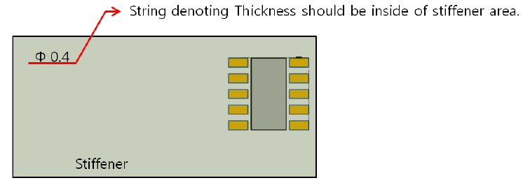
Figure 4.
Gas Hole Stiffener
If there are gas-holes under components, you can make rules for gas holes.
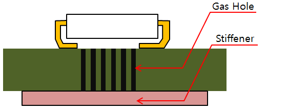
Figure 5.
- For Gas Hole Layer Selection, define gas-hole layer by selecting layer from layer list.
- Select Minimum Gas Hole Size, set minimum gas hole size.
- Select Check Existence of Gas Hole in Stiffener to check if there are gas hole in stiffener area.
- Select Clearance between Gas Hole and Stiffener to set the clearance value between gas hole and stiffener.