Features

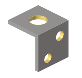
Detect, review, and manage geometric holes, fillets, flanges, and logos.

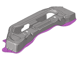
HyperWorks supports the detection and management of geometric holes (2D and 3D), fillets, flanges, and logos, as well as mesh holes and flanges. After a feature is detected, it will keep track of the geometry or elements defining it and automatically update if their topology is modified by another operation, like splitting the edges or surfaces defining it.

Create Features

Use the Features tool to find and create geometric features in the displayed model.

  1. From the Geometry ribbon, click the Features tool.


    Figure 1.
    If there are no Features in your model yet, the Feature Recognition Parameters dialog opens.
  2. Select the feature types you want to find and enter the minimum and maximum dimensions to include in the detection.
  3. Click Find to begin the detection process.
    Tip: Using larger tolerances will capture more features but will increase processing time.
  4. Optional: Click the Create Features satellite icon to manually create features.


    Figure 2.
    1. Select the config of the feature to be created.
    2. Select the type (Geometry or FE).
    3. Select the entities for the given config and type.
    4. Enter the feature parameters.
    5. Click Create to add the feature.
    Tip: Check Auto Compute to automatically compute the parameters.
  5. Optional: Click the List Features satellite icon to open the Features view in the browser.


    Figure 3.
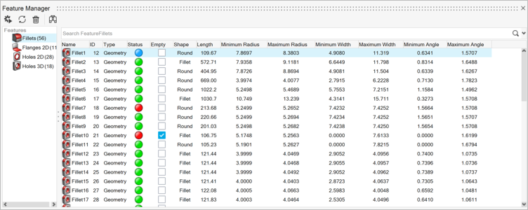
    Once the detection process is completed, the Feature Manager table opens.


    Figure 4.
  6. Use the Feature Manager to select, review, and edit the detected features.
    By now, the feature entities are already in the model and can be also accessed via the Model Browser or by selecting them directly in the modeling window.
    The Feature Manager uses the same search, filter, and sorting mechanisms as the Model Browser.
    Status
    Green – Auto detected
    Blue – Edited/Manually created
    Red – Invalid
    Empty
    A Feature that does not have any entities.
    Edit Feature
    1. Right-click on a feature in the manager.
    2. Select Edit Feature.
    Tip:
    • The same entity cannot be in two features of the same category. For example, the same surface cannot be in two fillets.
    • A Feature is removed if all its entities are moved to the another feature of the same category. For example, a fillet is removed if all of its surfaces are moved to another fillet.
    • Feature editing cannot be done if it’s not continuous. For example, feature editing cannot be done if a surface is removed from a fillet by making it discontinuous.
    The functions on the toolbar are:
    Rerun feature detection
    Return to the Feature Recognition Parameters dialog. Clicking Find in this dialog first clears all features in the model currently then re-detects them using the current parameters.
    Optional:
    • Select Delete existing features to delete existing features before detection.
    • Select Preserve edited features to preserve manually created/edited features before detection.
    Update
    Sync data and attributes for all, or individually selected features with their currently associated geometry or mesh.
    Tip: Re-evaluating features with this button also updates the Invalid column in the Feature Manager table. Features can be flagged as Invalid if their associated geometries have been deleted or modified in ways that cannot be referenced anymore. Invalid features can still be selected and used but may have some missing associated geometries or inaccurate dimensions.
    Delete all features
    Clears all features from the model. To remove individual features, select them anywhere and press Delete.
    Fit view to selected features
    Turn on to automatically fit the view to the features selected in the table.
Tip:
  • You can interact with features in the modeling window by setting the entity selector filter to Features with the mouse or by pressing the E key.
  • Selection conversion between features and surfaces, lines, or elements (depending on feature type) is supported by switching the filter type with an active selection.
  • Advanced selection methods are available for selecting features By Config, and geometry or mesh By Features.

Feature Types

HyperWorks supports the detection and management of the following feature types:

  • Geometry
    • 2D holes
    • 3D holes
    • Flanges
    • Fillets
    • Logos
  • Mesh (FE)
    • 2D holes
    • 3D holes
    • Flanges
  • Both (Geometry + Mesh Associativity)
    • 2D holes
    • 3D holes

2D and 3D Holes

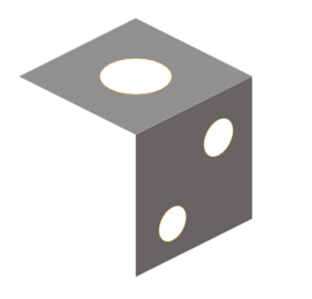
2D holes are surface holes with edges as perimeters and no height dimension. They can be detected as Geometry only, FE (Mesh) only, or both (associated). When all nodes of a meshed 2D hole are associated to geometry, the feature is categorized as Geometry type and shows the Associativity flag enabled.


Figure 5.

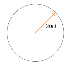
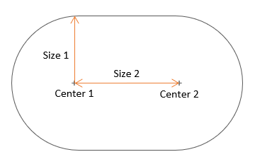
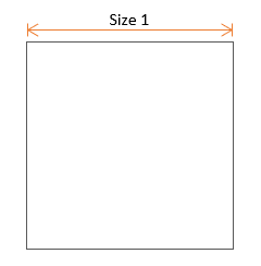
The following shapes and measured dimensions are supported for 2D holes:

Circular


Figure 6.
Rounded


Figure 7.
Square


Figure 8.
Rectangular


Figure 9.
General


Figure 10.
3D holes have surface faces along their height dimension, and surface edges at either the top side (blind) or top and bottom sides (through). Supported shapes and dimensions for either side are the same as 2D holes. Through holes with different top and bottom shapes are listed as General shape.


Figure 11.
Right-click on 2D or 3D holes for quick access to the following special actions:
  • Defeature - Selected holes are defeatured using the same commands used by Geometry > Defeature > Holes.
  • Fill - Selected holes are filled with a filler surface using the same commands used by Geometry > Surfaces > Patch.

Flanges


Figure 12.
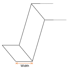
Flanges are surfaces along the edge of a part, with a width typically smaller than its length, as measured between its connected and free edges. Their measured dimensions are minimum and maximum width.


Figure 13.

Fillets


Figure 14.

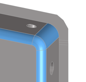
Fillets can be curved rounds (exterior) or fillets (interior) connecting surface edges in place of a corner. Their measured dimensions are minimum and maximum radius, minimum and maximum width, and minimum and maximum angle.

Right-click on fillets for quick access to the following special actions:
  • Defeature - Selected fillets are defeatured using the same commands used by Geometry > Defeature > Fillets.

Logos


Figure 15.

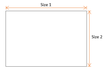
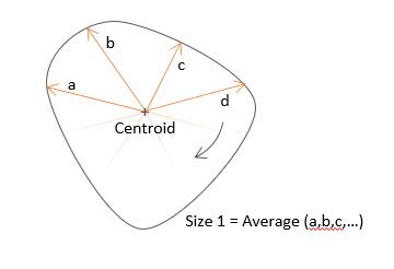
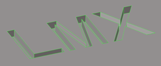
Logos are collections of surfaces representing symbols or letters that are embossed, etched, or machined into other surfaces. Their measured dimensions are size and height.

Right-click on logos for quick access to the following special actions:
  • Defeature - Selected logos are defeatured using the same commands used by Geometry > Defeature > Logos.