RD-E: 2602 Ductile Failure Model
Failure criteria defined with ductile failure model.
In Radioss, it is possible to simulate failure with a failure model. Johnson-Cook failure model is the most commonly used, which uses exponent function to describe the material failure behavior. /FAIL/TAB1 is the most sophisticated failure model to describe with simple curve input, which is more convenient. /FAIL/BIQUAD can describe with intuitive parameter input. Equivalent failure for these three failure models are discussed with one shell element and circular plate model.
Options and Keywords Used
- Johnson-Cook failure model (/FAIL/JOHNSON) with parameters
- Tabulated failure model (/FAIL/TAB1) with curve input
- Simplified nonlinear strain based failure (/FAIL/BIQUAD) with parameter input
- Imposed velocities (/IMPVEL)
- Material LAW2 (/MAT/LAW2 (PLAS_JOHNS))
- Rigid sphere (/RWALL)
Input Files
Model Description
LAW2 and Johnson-Cook Failure Model
The elasto-plastic behavior of the material is defined using the Johnson-Cook law (/MAT/LAW2 (PLAS_JOHNS)), with damage (maximum plastic strain, ). The failure model /FAIL/JOHNSON is independent from the material law and the hardening model.
- Current damage and is in range of .
- Increment of plastic strain during the loading.
- Stress triaxiality (or normalized mean stress) .
- , and
- The first three parameters for Johnson-Cook failure model.
The strain rate and thermo-plastic effects are not taken into account in this example. Thus, only three parameters are required (, and ).
For more information about this failure model, refer to Johnson-Cook Failure Model in the Theory Manual and /FAIL/JOHNSON in the User Guide.
- The failure plastic strain in /MAT/LAW2 is not taken into account.
- In addition to the Johnson-Cook failure model, the maximum stress and the failure plastic strain are activated.
- Shell element is deleted, if damage for one layer (Ifail_sh = 1).
- The layer stress tensor is set to zero and the shell element is deleted, if damage for all layers (Ifail_sh = 2).
| Ifail_sh = 1 | Ifail_sh = 2 | |||
|---|---|---|---|---|
| /FAIL
+ , |
/FAIL Only | /FAIL
+ , |
/FAIL Only | |
| Johnson-Cook failure model | = 0.11 = 0.08 = -1.5 = 0.151 |
= 0.09 = 0.08 = -1.5 |
= 0.11 = 0.08 = -1.5 = 0.151 |
= 0.09 = 0.08 = -1.5 |
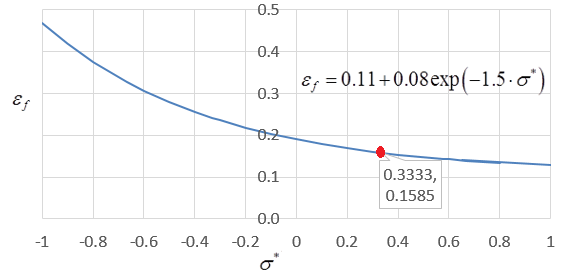
Figure 1.
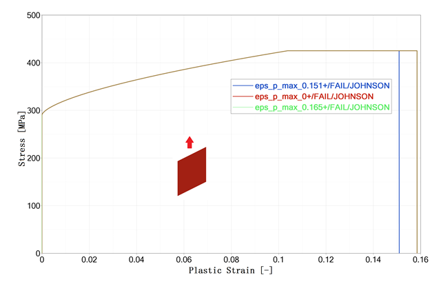
Figure 2.
Ductile Failure Models
In /FAIL/TAB1 and /FAIL/BIQUAD it is also possible to have equivalent , as in /FAIL/JOHNSON.

Figure 3.
- /FAIL/TAB1 Example:In the /FAIL/BIQUAD failure model, it is also possible to describe with intuitive input parameter c1, c2, c3, c4 and c5 as:
- Parameter
- Description
- c1
- Failure strain at uniaxial compression test, where
- c2
- Failure strain at pure shear test, where
- c3
- Failure strain at uniaxial tension test, where
- c4
- Failure strain at plainstrain tension test, where
- c5
- Failure strain at biaxial tension test, where
The parameter c1, c2, c3, c4 and c5 are from curve (created from above Johnson-Cook failure) in /FAIL/BIQUAD, and then the same failure as in /FAIL/JOHNSON, observed with /FAIL/BIQUAD.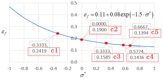
Figure 4. - /FAIL/BIQUAD Example:The same results show in /FAIL/JOHNSON, /FAIL/TAB1 and /FAIL/BIQUAD, with the equivalent failure curve.
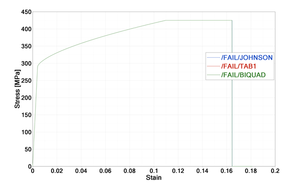
Figure 5.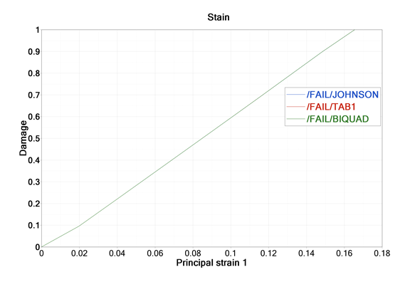
Figure 6.In /FAIL/BIQUAD actually use parabolic function to reproduce the failure curve cording to input c1, c2, c3, c4 and c5. In fact, the for /FAIL/BIQUAD used in Radioss may slightly different than Johnson-Cook failure model or TAB1 model. As in this example, in /FAIL/BIQUAD is printed in start output *0000.out file.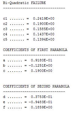
Figure 7.Use the above a, b, c, d, e, f coefficient from start output file in below parabolic functions from /FAIL/BIQUAD, the is:(4) 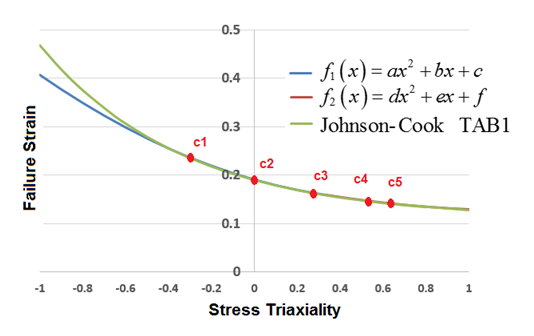
Figure 8.At point c1, c2, c3, c4 and c5 are the same; but outside these points, there are some differences. In the simple one element example (uniaxial test), it does not involve other stress state during simulation. Therefore, it shows no difference between these three failure models.
Results
| Model Setup | Failure Strain |
|---|---|
| = 0.151 in
LAW2 /FAIL/JOHNSON (with ) |
By 0.151 ( in LAW2) |
| = 0.165 in
LAW2 /FAIL/JOHNSON (with ) |
By 0.1585 (failure defined in /FAIL/JOHNSON, where ) |
| = 0 (no failure strain) in
LAW2 /FAIL/JOHNSON (with ) |
By 0.1585 (failure defined in /FAIL/JOHNSON, where ) |
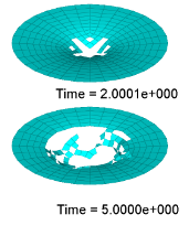
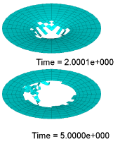
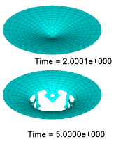
- Ifail_sh =1: if strain in one integration point reached the criteria
- Ifail_sh =2: if strain in all integration point reached the criteria
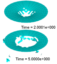
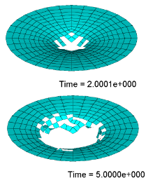
It shows less failure in plate with Ifail_sh =2, than in Ifail_sh =1.
| Ifail _sh=1 in LAW2 | Ifail _sh=1 | Ifail _sh=2 in LAW2 | Ifail _sh=2 |
|---|---|---|---|
 |
 |
 |
 |
Influence
| Johnson Failure
Ifail_sh=1 |
TAB1 Failure
Ifail_sh=1 |
BIQUAD Failure
P_thickfail=1/N |
|---|---|---|
 |
 |
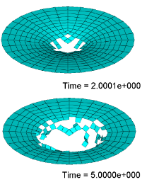 |
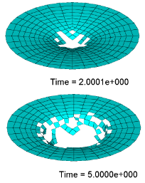
For /FAIL/JOHNSON and /FAIL/TAB1 the option Ifail_sh in these models is to control the element delete criteria. In this plate model, Ifail_sh=1 means the element is deleted once damage criteria is reached in just one integration point.
In /FAIL/BIQUAD the equivalent option Pthickfail is to control the element deletion. It defines element deletion criteria with percentage of through thickness integration points. In this plate example, 5 integration points are defined through thickness (N=5 in /PROP/SHELL). Set Pthickfail=1/5, which means element deleted if one of the 5 integration points reaches the damage criteria.
Conclusion
Failure model Johnson-Cook, TAB1 and BIQUAD (which use failure curve) are studied here with one shell element and also circular plate.
Failure could be defined in material model and in failure model at same time. Compare different combinations of failure definition in LAW2 and in Johnson-Cook failure model, it shows the element damaged once first reach any criteria defined in material model or failure model.
Equivalent failure criteria could be generated with Johnson-Cook, TAB1 and BIQUAD, but for BIQUAD there might be a slight difference since it uses two parabolic functions.
Pthickfail in /FAIL/BIQUAD is similar to Ifail_sh, but is more flexible since it uses a percentage of thickness to define element deletion criteria.