PP Card
This card defines the phase shift of the excitation between one unit cell and the next for periodic boundary conditions. The unit cell for a PBC calculation is specified with the PE card.
On the Home tab, in the Planes / arrays
group, click the ![]() Periodic boundary
icon. From the drop-down list, click the
Periodic boundary
icon. From the drop-down list, click the ![]() Periodic phase (PP) icon.
Periodic phase (PP) icon.
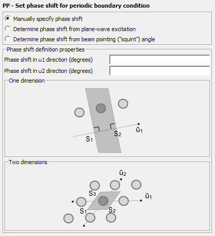
Figure 1. The PP - Set phase shift for periodic boundary condition dialog.
Parameters:
- Manually specify phase shift
- The phase shift is manually specified.
- Determine phase shift from plane-wave excitation
- When a plane wave is used as excitation the phase difference between the cells cannot be specified, but is determined by the excitation.
- Determine phase shift from beam pointing (“squint”) angle:
- The phase shift is determined by specifying the theta and phi angle of the “squint” angle.
- Phase shift in direction (degrees)
- Phase shift in the first direction, .
- Phase shift in direction (degrees)
- Phase shift in the second direction, .
One dimension:
- Theta angle (degrees)
- Orientation of the squint angle. The angle, theta, in degrees is the angle between the squint angle and the plane defined by the vector.
Two dimensions:
- Theta angle (degrees)
- Orientation of the squint angle. The angle, theta, in degrees is the angle between the squint angle and the plane.
- Phi angle (degrees)
- Orientation of the squint angle. The angle, phi, in degrees is the angle between the squint angle and the plane defined by the vector.