ACU-T: 3200 Radiation Heat Transfer in a Simple Headlamp using the Enclosure Radiation Model
Prerequisites
This tutorial introduces you to the workflow for setting up a thermal radiation problem in a headlamp using the enclosure radiation model in HyperWorks CFD. Prior to starting this tutorial, you should have already run through the introductory tutorial, ACU-T: 1000 Basic Flow Set Up, and have a basic understanding of HyperWorks CFD and AcuSolve. To run this simulation, you will need access to a licensed version of HyperWorks CFD and AcuSolve.
Prior to running through this tutorial, click here to download the tutorial models. Extract ACU-T3200_headlamp.x_t from HyperWorksCFD_tutorial_inputs.zip.
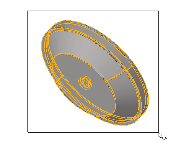
Problem Description

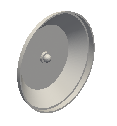
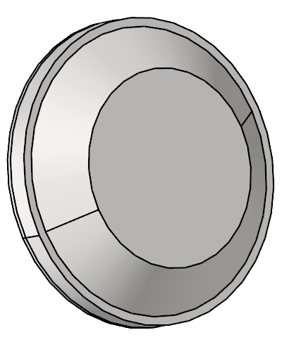
Figure 1.

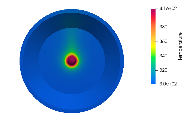
Figure 2.
Start HyperWorks CFD and Create the HyperMesh Model Database
Import and Validate the Geometry
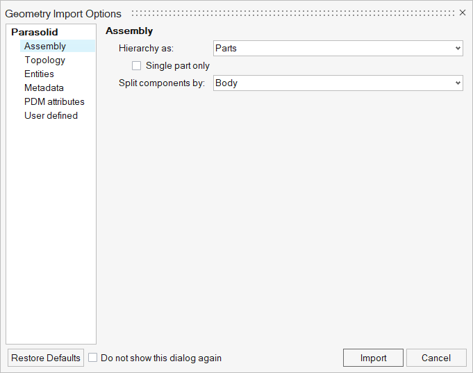
Import the Geometry
Validate the Geometry
Set Up Flow
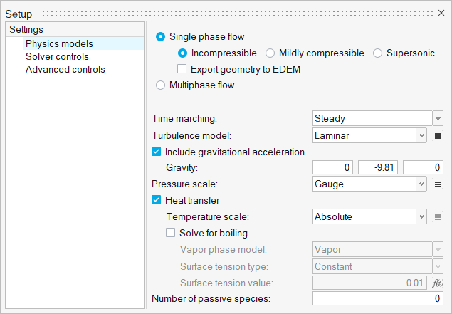
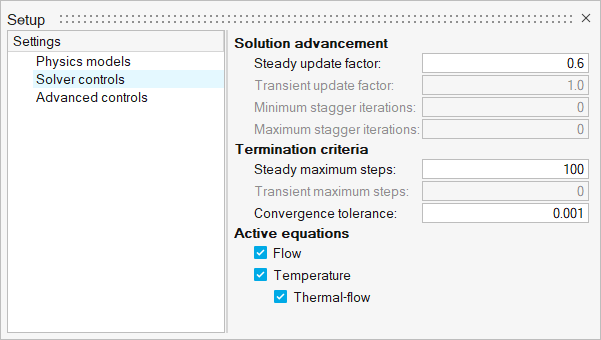
Set the General Simulation Parameters
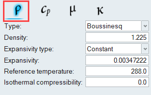
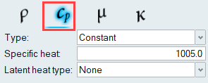
Define the Material Models
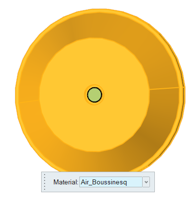
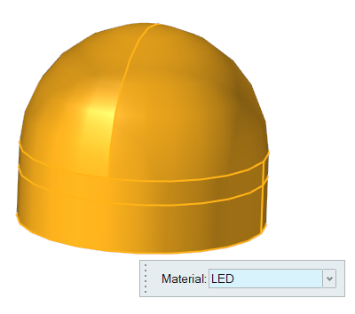
Assign Material Properties
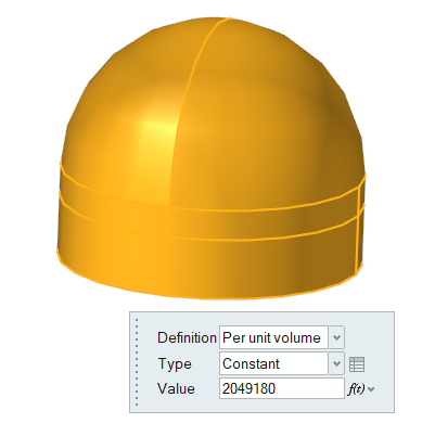
Define the Heat Source
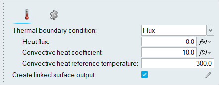
Define Flow Boundary Conditions
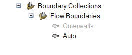
In this problem, all the surfaces are walls and will therefore be assigned the default wall boundary condition. The outer walls of the headlamp will be given a no-slip wall boundary condition with a convective heat flux boundary condition.
Set Up Radiation
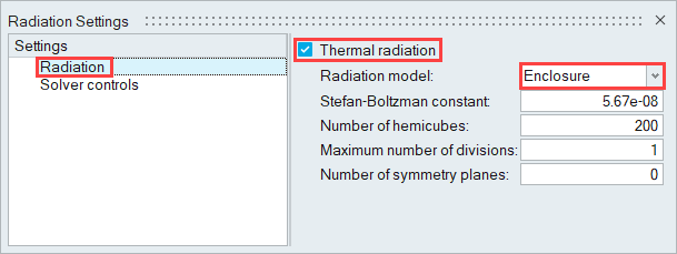
In this step, you will specify the parameters related to the thermal radiation setup.
Define Radiation Model Settings
Define the Emissivity Models
Assign Surface Finish Models
Generate the Mesh
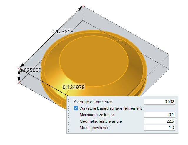
In this step, you will define the mesh controls and then generate the mesh.
Define the Surface Mesh Controls
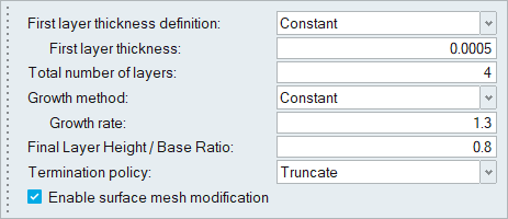
Define the Boundary Layer Controls
Define the Volume Mesh Controls
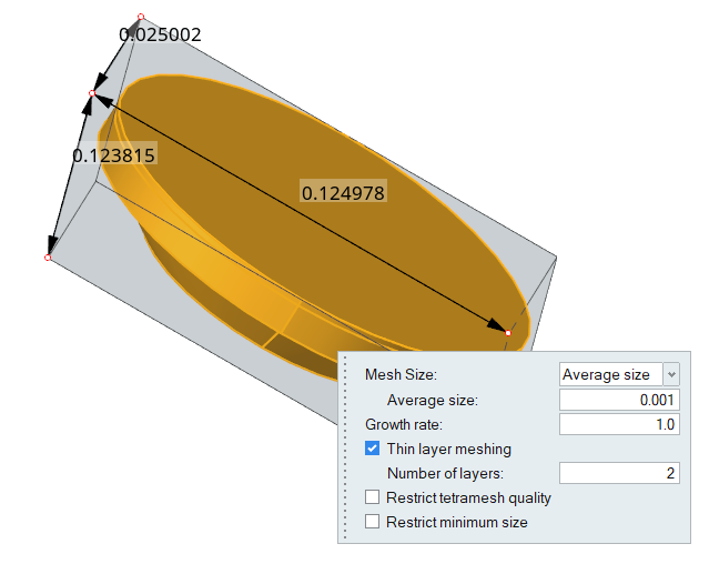
Since the thickness of the housing and the lens solids are small, you will use the thin layer meshing tool so that when the volume mesh is generated, there will be two layers across the thickness of those solids.
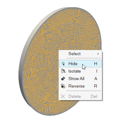
Generate the Mesh
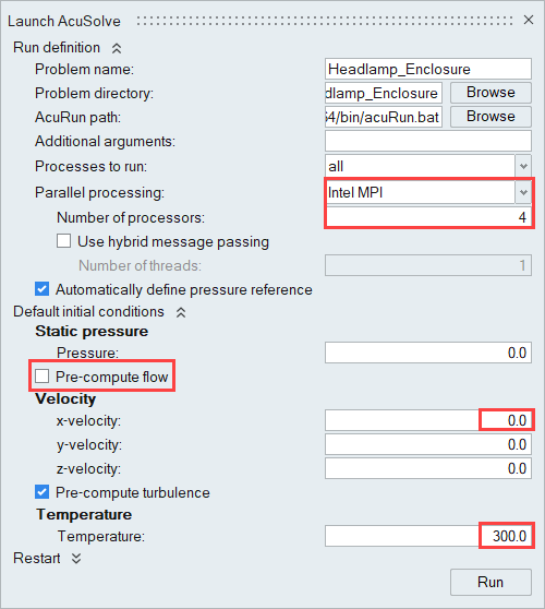
Run AcuSolve
Post-Process the Results with HW-CFD Post
Summary
In this tutorial, you learned how to set up and solve a radiation heat transfer problem in a headlamp using the enclosure radiation model in AcuSolve using HyperWorks CFD. You started by importing the headlamp geometry file, then you set up the simulation parameters and boundary conditions. Once the solution was computed, you processed the results using the Post ribbon where you created contour plots of temperature.

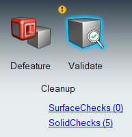
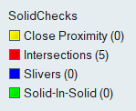
 and
and  to review each
error.

