Laminate Tool
Use the Laminate tool to calculate fiber angles and thickness changes with respect to an element material system.
This tool creates a distribution table of drape angle changes, change the thickness of each ply, and flatten the shape of a ply that needs to be fabricated before laying on the mold.
Fiber angle changes with respect to a material system when a flat composite sheet is
laid on surfaces of a part which is highly curved in bi-directions. This also
changes the ply thickness. It is no longer the nominal ply angle ( 0,45,-45, 90). If
the change in angle or thickness is significant, it will lead to a change in the
stiffness of a part.
Note: The Laminate tool is available in the OptiStruct and Abaqus user
profiles.
Note: This tool requires installation of Draping Tools by
Anaglyth.
-
In the Drape Calculation tab, define draping simulation settings.
-
Using the Application Direction selector, select a vector to indicate
how a ply is placed. If this direction (vector) is not selected, the
element normal will be used as the application direction.
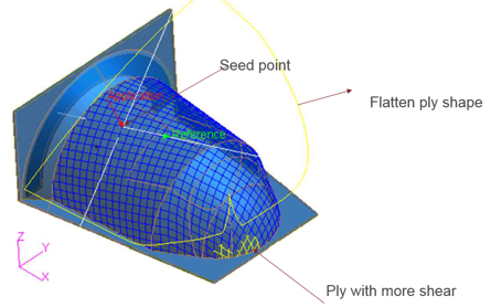
Figure 1.
-
Using the Application Direction selector, select a vector to indicate
how a ply is placed. If this direction (vector) is not selected, the
element normal will be used as the application direction.
-
In the Review tab, select a review option to read the results.
Option Description Drape Lines Initially an unidirectional ply start with a 90 degree angle between the weft and wrap lines. As the ply is draped over a curved surface, this angle changes. If the shear is more than max strain, than the color changes from blue to yellow to red. 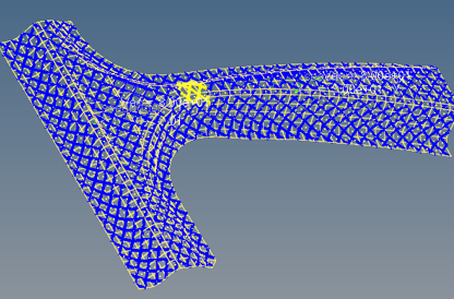
Figure 2.Flat Lines Review the flat ply shape that is needed to cover the surface. 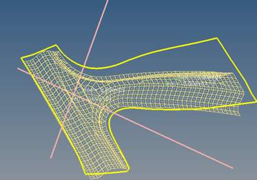
Figure 3.Drape Thickness Contour the distribution of thickness changes. 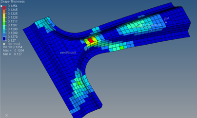
Figure 4.Drape Orientation (shear) Contour the shear (angle changes from 90 degrees). 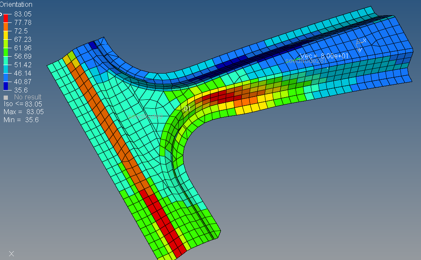
Figure 5. -
In the Export tab, export the flatten ply shape as geometry (STEP
format).
The Flat ply shape can be exported one ply at a time as STEP geometry.
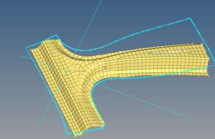
Figure 6.