HM-3560: Basics of Domains and Handles
In this tutorial you will create domains and handles, and morph the model.
This exercise uses the morphing_1.hm file, which can be found in the hm.zip file. Copy the file(s) from this directory to your working directory.
Open the Model File
In this step you will open the model file, morphing_1.hm.
Auto Generate Domains and Handles
In this step you will auto generate 2D domains and handles.
Move Elements into a New Domain
In this step you will move elements into a new 2D domain.
-
Click
 to clear the elements that were already
selected.
to clear the elements that were already
selected.
-
Using elems >> by window, select the elements indicated
in the following image.

Figure 1.
Split the Edge Domain
In this step you will split the edge domain of the radius to have more control when morphing.
-
With the domain selector active, select the edge domain of the part's radius as
shown in the following image.
The node selector automatically becomes active once the edge domain is selected. Click the domain selector to make it active and see that you selected the desired edge domain.
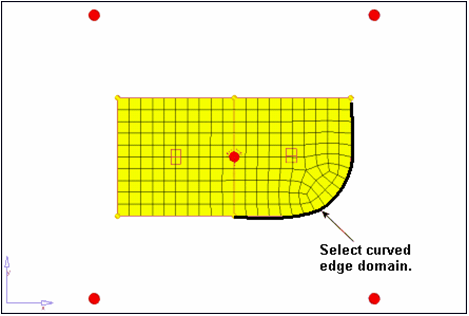
Figure 2. -
Select the node on the positive Y-axis end of the radius, as indicated in the
following image.
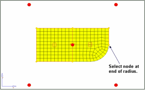
Figure 3. -
Repeat the above process to further split the edge domain of the radius, this
time at the node indicated in the following image.
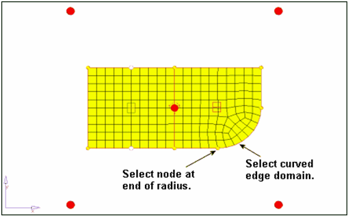
Figure 4.
Add Local Handles
In this step, you will add local handles to the 2D domain on the part's left side.
-
Select the 2-D domain on the part’s left side by selecting its red icon, as
indicated in the following image.
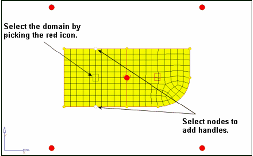
Figure 5.
Perform Basic Morphing
In this step, you will perform basic morphing to understand how domains and handles interact with each other and the mesh.
-
Release the mouse button to complete the morphing operation.
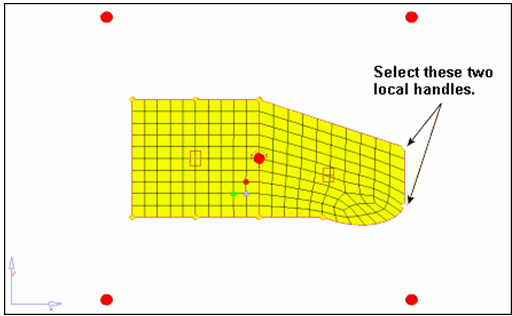
Figure 6. -
Click to clear the selected handles.